The mystery of adding LED lights to a modern BMW with CAN Bus (Controller Area Network) electrical system is easy to resolve.
The “smart” CAN Bus smells a rat when you pop in an LED brake light or turn signal.
The LED will work, but you’ll get the malocchio warning light on the dash.
And unless you have a Grandma who knows the secret anti-malocchio incantations, believe me, you’ll want to avoid it.
The solution is easy: add a load resistor to the plumbing.
Rick is busy trying to convert webBikeWorld to the new responsive design.
So he asked me to install a load resistor on the BMW F800S and write up a little report on adding an LED tail light/brake light.
He bought a box of goodies for the F800S back in the Fall of 2014 and the box and the bike got caught up in the arctic winter of ’14, both collecting dust.
Now that warm weather is here, it’s time to start farkling again.
We’ve done plenty of LED light reviews on webBikeWorld that have covered the LED brake light pretty much every way you can think of.
But he bought yet another pair, just to see if there was anything new, so we’ll take a quick look at that also.
Since this is a quickie, let’s do another one of the photo-heavy reviews.
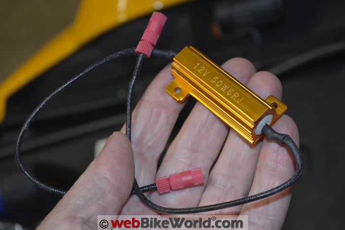
You’ll need a 50 Watt, 6 Ohm resistor with built-in heat sink. Cost: anywhere from $3.00 to $6.00. Or, make your own.Installation
I’m not an electrical genius by any means, but it’s my understanding that the LED light uses a lot less juice than the stock incandescent 21/5 Watt bulb on the older/newer BMW motorcycles.
So the CAN bus throws an error if you plug in an LED because the system senses a light out condition.
To solve this, you have to add some resistance to the line to fake out the CAN bus. There are several different types of resistors you can buy to do this and it’s probably easy enough to make one yourself with a resistor.
All you have to do is tap into the ground and tail light (not brake light) wire if that’s where you’re adding the LED.
Add the resistor across the circuit, which adds a load (resistance) to the circuit so that the CAN Bus senses the load and thinks everything is OK.
By the way, this is a similar electrical issue as the diode that must be added to the electrical system on many motorcycles when installing LED turn signals.
ssee the DR650 Blog article about replacing 1156 bulbsfor more info and photos of the diode replacement, which you can easily make yourself.
It doesn’t matter which wire of the load resistor unit is connected, as there’s no positive or negative. Of course, you’ll use the Posi-Taps sold by webBikeWorldto tap into the line.
Don’t use the cheap connectors you get with the load resistor kit — they’re not designed for use with a motorcycle, due to the vibrations.
Rick had a couple of these high-quality “Cute Queen” (yes, that’s the name) 50 Watt, 6 Ohm resistors, $5.49 for two.
They’re probably way over-built for what they are and the anodized aluminum housing acts as a heat sink. Supposedly, these get pretty hot, so you’ll want to be careful where you mount it.
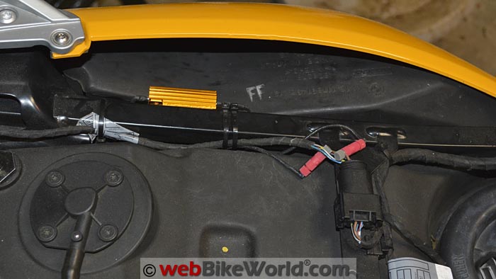
On Rick’s BMW F800S (Blog), I used some double-sided tape with some 3M medallion adhesive and mounted it to the side of the rear frame member, away from the plastic and the under-seat fuel tank.
Also on the F800S, F800ST and F800R, the red/silver/yellow wire is the tail light and brown is ground (earth) on most BMWs. Fortunately, the rear light wiring harness is very easy to access — at least on this F800S — as it’s right under the seat.
I didn’t want to strip the factory tape, so I tapped into the wires up near the connector.
Here are some photos:
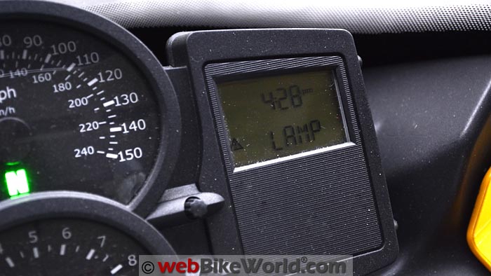
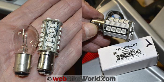
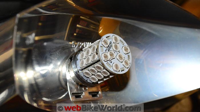
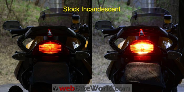
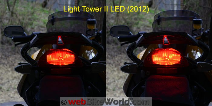
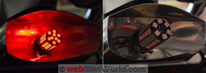
The BMW CAN bus gives a “LAMP” error if you use an LED without a load resistor, although the light will still work. The “Cute Queen” LED load resistor mounted on the sub-frame and tapped into the ground and tail light wires. The original 21/5W incandescent, with a 2012 version of the LED tower. The 1157 R26-CBT on the right doesn’t work in the BMW. Here’s the 1157 R45-T LED replacement that works in the BMW. LEDs still have a hard time matching incandescent output when the reflector and light system isn’t designed specifically for LEDs. Here’s the stock 21/5W incandescent tail light (running light) on the left and on the right with the brakes on. This is the LED “Light Tower II” from the 2012 LED light replacement comparison review. It doesn’t match the stock incandescent for output.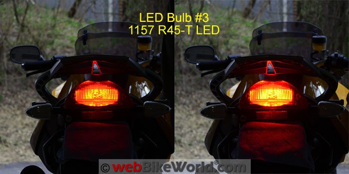 The Superbright LEDs 1157-R45-T sort of matches the incandescent output, so that’s what we used. It is rated at 220 lumens and has 45 LEDs in a 360-degree orientation. Always use the same color LED as the lens; in this case, a red LED to match the red tail/brake light lens. The 1157-R45-T on the left and 1157 R26-CBT on the right. This is as bright as the R26-CBT gets and we’re not sure why.
Conclusion
Installing a load resistor is — or should be — very easy. The only trick is knowing the color of your ground and tail light (or turn signal) wires and then being able to find and access the wires in the wiring harness.
But be careful: LEDs (when used in a stock reflector) still don’t always match the output of that simple, basic, buck-fifty incandescent 21 Watt bulb, as you can see in the photos above.
By the way, you’ll need a load resistor for every circuit. For example, if you were going to add LEDs to each turn signal, you’ll need four load resistors, one for each turn signal.
Some of the custom LED turn signals (and tail/brake lights) have built-in load resistors, like the ridiculously expensive BMW LED turn signals we reviewed for the F800S.
The “Cute Queen” load resistor in the heavy-duty aluminum housing is available under a bunch of different brand names; they’re probably all made in the same factory in China.
They’re built like a tank and the aluminum acts as a heat sink to dissipate the heat build-up from the electrical resistance…although it’s hard to believe there can be that much resistance in what was a 21 Watt tail light with an 18 gauge wire.
Anyway, that’s how you do it, there’s no mystery involved really. Not sure if this also works on the latest BMW motorcycle models, but most of them have LEDs right from the factory anyway.
If you have any tips or info on this, send them to editor@webbikeworld.com
More: BMW F800S Blog | wBW Motorcycle LED Light Reviews

Review Date: April 2015
Owner Comments and Feedback
See details on submitting comments.
From “F.M.” (April 2015): “I may have an answer as to why your 1157 R26-CBT bulb was so dim. The 6 ohm load resistor in parallel with the LED is probably causing the voltage to drop too low.
That LED bulb in parallel with the 6 ohm resistor probably results in a resistance of 5.4 ohms, meaning that the bike is asked to supply 36 watts of power (at 14V, which is pretty typical voltage for a running bike).
That’s 2.6A coming through some pretty long and thin wires, and I bet that the voltage is dropping too low. Measure the voltage across the resistor with the brakes on and that LED bulb in place.
You might try putting two of the load resistors in series. That gives you 12 ohms.
In parallel with the 1157 R26-CBT bulb, you should get a power draw of just under 20W at 14V, which will probably satisfy the bike’s bulb monitoring, reduce voltage drop substantially, while cutting the resistor temperature way down.
“Not sure if this also works on the latest BMW motorcycle models, but most of them have LEDs right from the factory anyway.”
Using those load resistors on a bike designed for LEDs would be a very bad thing. The bike would be trying to supply an order of magnitude more current than it was designed to supply.
Editor’s Reply: Thanks for the info. Actually, that photo was taken before the load resistor was installed. Not sure why the light doesn’t light when it’s in the receptacle because it lights when connected directly to the battery.
We have run into this problem before, sometimes the lamp base isn’t quite standard and that one has some soldering around the bottom, which may be preventing it from seating correctly.
Also, we didn’t mean to imply that a load resistor should be used with LEDs on a vehicle that has LEDs but that a load resistor isn’t needed when LEDs are factory installed.
From “E” (April 2015): “I have a question about your article ‘LED Load Resistor for BMW CAN bus’. I read the article twice, but couldn’t figure out how the load resistor is supposed to be connected into the circuit: In series, or in parallel?
That is, should it be connected so that the electricity flows: power > load resistor > LED > ground (series)?
Or should the resistor be connected across the load, between the + and – terminals on the LED (parallel)? Thanks for the article!”
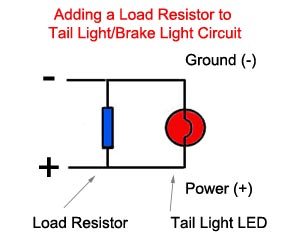
Editor’s Reply: Good question, Mad Dog should have explained it better. Basically it just adds a load to the + and – wires that go to the tail light, so you splice the load resistor across those two wires before they get to the light.
The CAN Bus senses the resistance and thinks everything is OK, even though the LED uses a tiny amount of power compared to the incandescent. I just added a diagram to show this and an explanation in the article.