Repairing the Digital Clock – DR-Z400S
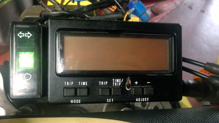
The Suzuki DR-Z400S clock is part of the electronic dashboard display.
Apparently, the clock can go bad while the rest of the display still functions.
A completely new digital instrument cluster will cost plenty, but it’s possible to fix the clock.
Here’s how I did it.
Regular webBikeWorld visitors may have seen my recent posts on the Sena SMH10 intercom (review).
There are two stories, one is “5,000 Miles With the Sena SMH10” on the Trans-Labrador Highway.
Another was last year’s “4,000 Miles With the Sena SMH-10 on the Trans-America Trail“.
During that last Trans America Trail outing, we found ourselves in a little over our heads on some of the terrain; I had my BMW R1150GS (review) overloaded just a tad for the trip, which could have been the cause of some problems.
But even more, I lacked the off road riding skills needed to navigate such a heavy beast over some of the trails we encountered along the way.
No one got hurt and the bikes acquired a few more “battle scars”…but then isn’t that what an adventure is all about?
We had to stop when we reached Silverton, Colorado because my riding buddy had a wedding to attend in Denver (a precursor to the trip) and, unlike me, he had to return to work.
So with what we considered “unfinished business” on the Trans-America Trail, we decided to return in the summer of 2013 and finish the trail to its end at the Pacific coast in Oregon.
But, this time it will be on much smaller and lighter bikes since Glen’s research shows we’re in for more difficult terrain; i.e., more sand and large rocks.
With that in mind Glen and I set out to locate and buy a pair of used, worthy steeds for the challenge of riding the remainder of the trip. But, there was a catch.
We would also have to ride these bikes back from Oregon to our drop-off point in southeast Colorado, so the bikes would have to be street legal and able to safely reach highway speeds.
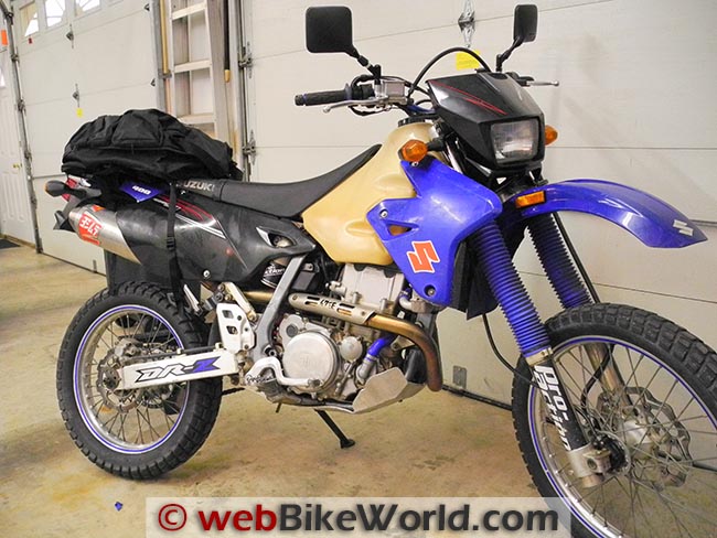
Glen found a Kawasaki KLX 250 and after some searching, I bought a 2003 Suzuki DRZ400S which already had a bunch of accessories on it that would be needed for the trip.
This included an oversize fuel tank, rim locks, stronger handlebars, a bash plate, radiator guards and aftermarket heated grips just to name a few.
I did have to drive 5 hours each way to retrieve it, but I think it was worth the trip especially after looking at some of the junk that people were selling closer to home for, quite frankly, ridiculous prices.
Where to Buy Suzuki DR-Z400S Clock
Check Reviews & Prices on AmazonSee More: Motorcycle Accessories, Motorcycle Tire, Motorcycle Helmets
Suzuki DR-Z400S Clock Problems
One of the “quirks” that the previous owner pointed out before I bought the bike was that the clock would re-set itself to 1:00 when the ignition was turned off. This was not a big concern to me, but once I had the bike home it really became a curiosity.
Was it a simple matter of a blown fuse, or a loose connector? He had mentioned that he had read where the Suzuki DR-Z400S clock problem was a solder connection or something similar.
My searches yielded little, other than quite a few owners reported having the same failure shortly after a battery replacement. The usual fix required replacement of the speedometer assembly — and that ain’t cheap.
Back in the late 80’s, we had a common complaint of a total failure of the climate control on some of the vehicles I was working on. Many of these cars were out of warranty and the climate control push-button assembly was made in Germany and it was quite expensive.
We had found that when we gently flexed the Printed Circuit Board, the system would cut on and off.
This we traced to cracked soldered connections where the main board was joined to a smaller perpendicular board where the connectors from the body harness attached.
When the components would flex do to temperature changes the cracks would widen and cause an “open” in one or several circuits. With only a few minutes time and some fine silver solder we were able to repair and reinforce these points.
This resulted in an incredible savings for the customer (who were more than happy) and I never saw one come back.
Could the DR-Z400S clock problem be something similar?
 Rusted connectors were an obvious clue.
Isolating the Problem
Testing found a secure battery “hot” and ground at the four-pole connector going into the speedometer assembly, so I decided to remove and open the speedometer up to take a gander at the soldered connections, etc. inside.
Now, I’m no electronic genius by any means, but I do have an understanding of electronics and have fixed quite a number of devices over the years by simply looking closely at connections, both wired and soldered.
The instrument display housing is held together with several Phillips head screws, after which the internals come right out as one piece.
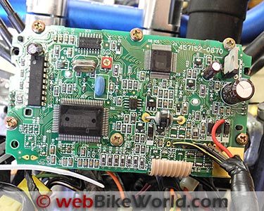
A small three-pin connector that powers the inductive speedometer pick-up, driven by the speedometer cable, had to be disconnected. Then the main printed circuit board (PCB) could be removed from the back housing.
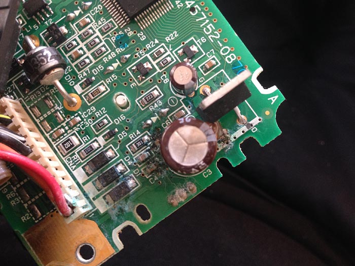
Peering around I noticed some grey “slime” on a multi-pin connector which fastened the incoming harness to the PCB. My experience told me that this is always a bad sign — a signal of corrosion and usually failing contacts.
The one socket with the most corrosion was the “hot” wire from the battery.
At first I thought this multi-pin connector was a “female” type and was pushed onto “male” pins soldered to the PCB. But alas, the wires had crimped on ends with needle thin points that were in turn soldered to the PCB.
This made no since to me, why not simply solder the wires directly to the board?
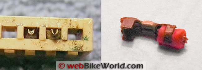
Removal of the connector required the use of a soldering pen and my de-soldering tool. The pin for the “hot” wire was so corroded it broke early in the operation. Now I was committed.
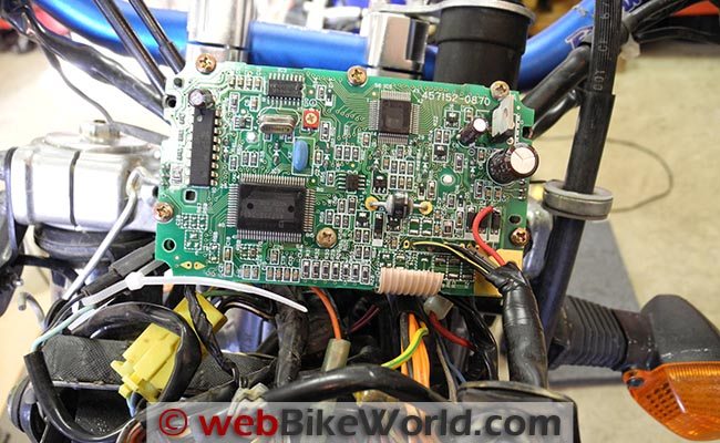 The circuit board after the fix.
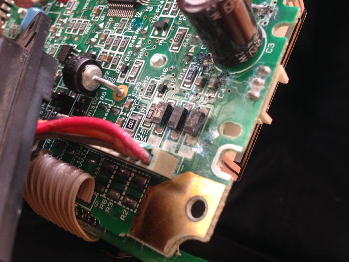
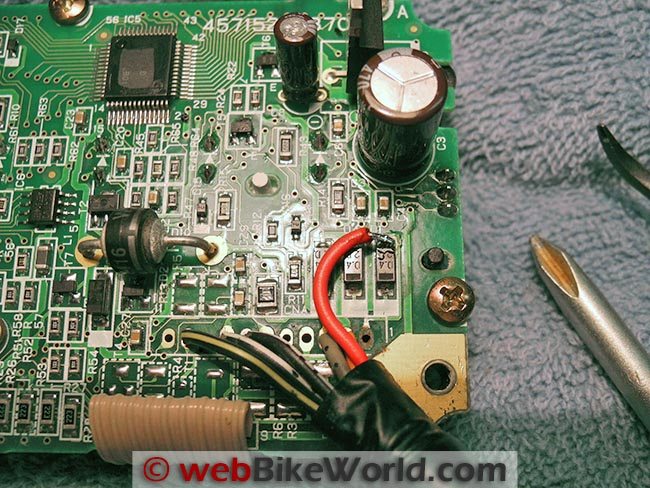 Close-up of circuit board.
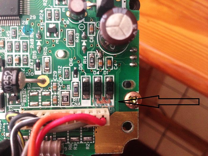
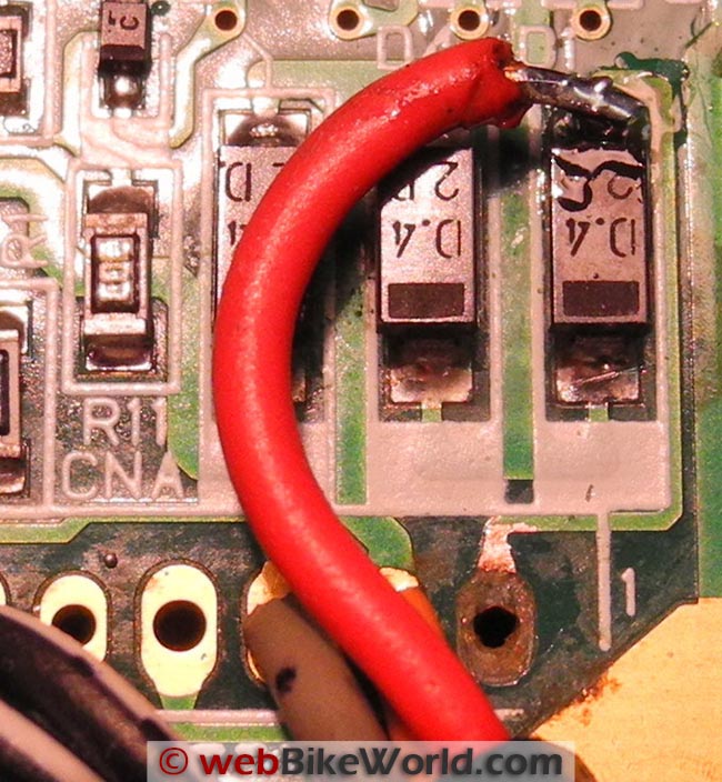 Super-close up of the soldering fix.
Where to Buy Suzuki DR-Z400S Clock
Check Reviews & Prices on AmazonSee More: Motorcycle Accessories, Motorcycle Tire, Motorcycle Helmets
The Fix…
With the pins removed and on close inspection I could see the contact point on the PCB for the “hot” supply was badly corroded and actually missing on one side.
Whereas I could solder the other wires directly to the PCB I wouldn’t be able to do so with the “hot” wire so I decided to simply run it to the next solder point for that circuit. With the end of the wire tinned and a piece of tape to hold it in place I tacked it to the next solder point.
The photos probably don’t show it well, but these wires and solder points are very small and I had a tough time seeing them and keeping the solder within the necessary tiny boundaries.
The remaining wires were trimmed and soldered directly to the PCB resulting in what I think is a far strong connection than stock.
A small dab of silicone sealant has placed on the “hot” wire along its length to secure it to the PCB and keep it from vibrating and possibly breaking off.
Before putting it all back together again I took it out to the garage and plugged it into the harness to see if things still worked and I hadn’t ruined a perfectly good speedometer assembly.
Much to my delight everything worked with the key (although I wasn’t able to ride it for a few days to test the speedometer) and the clock was working.
Did It Work?
I set the correct time on the clock, turned the key to off and then waited a few minutes.
I turned it back on to see if the clock was keeping time. It was! But, the real test would be if it held after a week or so with the occasional on-off cycling of the key.
It’s been over a week now and I’m happy to report that the clock has been keeping time and functioning perfectly ever since. Oh yeah, all of the other functions, including the speedometer, operate fine too!
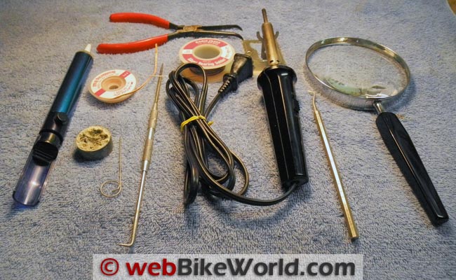 Tools used for this project.
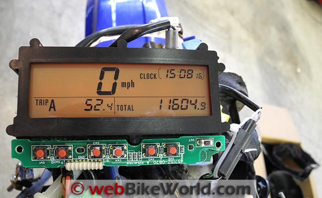 Everything back to “normal”!
Where to Buy Suzuki DR-Z400S Clock
Check Reviews & Prices on AmazonSee More: Motorcycle Accessories, Motorcycle Tire, Motorcycle Helmets
Don’t Forget to Clean
During disassembly I noticed signs of dust and crud inside the speedometer housing. This was cleaned out with Q-Tip swabs and rubbing alcohol.
The original gasket was deteriorated so a thin bead of black silicone sealant (to match the housing) was placed along the edge where the main housings came together.
I ran another small bead on the outside along the seam and around the rubber grommet where the wires pass through the back of the housing. I suspect moisture got inside the housing and attacked the wiring.
Also, a zip-tie was added to hold the wires coming out of the housing to the mount bracket bolted to the back of the housing in order to eliminate any strain of the wires on PCB.
Conclusion
Pardon the pun, but only time will tell if the repair holds up to the punishment of off road riding. The weak link will probably be my soldering work. It may not be pretty, but then I’ve never had a repair of this type fail.
OK, now for some disclaimers: This is not an approved repair and there is obviously no guarantee that if your clock isn’t functioning that this repair will fix it.
My report simply describes what I found to be the problem with my particular DR-Z400S and my method of repair.
This repair is not for the timid because it is easy to ruin a working speedometer assembly if you make a mistake when soldering. But then there is that old saying “Nothing ventured, nothing gained”…
If you have feedback on this article or if you have some other tips on maintaining the electronics, electrics or anything else on the Suzuki DR-Z400S, don’t hesitate to contact us!
Publication Date: February 2013
More wBW: Suzuki DR-Z400S Blog
Master Listing of All wBW Motorcycle Product Reviews
Where to Buy Suzuki DR-Z400S Clock
Check Reviews & Prices on AmazonSee More: Motorcycle Accessories, Motorcycle Tire, Motorcycle Helmets
Owner Comments and Feedback
See details on submitting comments.
From “A.D.” (June 2015): “I have read your article on your clock repair on the Suzuki DRZ 400. I have a similar problem.
My screen displays that the back-light is working but the rest of the screen is dead. I have found corrosion on my PCB and cleared it with rubbing-alcohol. But the screen remains dead, will it help to remove my red “hot” wire and solder it the same as you did?”
Chris’ Reply: Sorry for the slow reply, but the Mrs. and I were on a road trip and got back a couple of days ago. I no longer have the DR (and wish I still did) and don’t have the manual either, so I’m kind of at a loss in helping you with your problem.
I had an obvious connection problem on mine and was able to bypass the damaged area on the circuit board.
All I can suggest is to look at all of the connections very carefully and the soldered points on the PCB. Maybe you’ll find something amiss.
I used this illuminated microscope and it usually gave me a clear enough view of the solder points. Everything moves in reverse though as you scan. Good luck!”
Follow-up From Alex (July 2015): “Thanks for your reply and posting. Always a good feeling to help others with the same problem. I found a solution to my problem and my speedo is working 100% for almost 2 months without any interruptions.
Attached is a picture of only scraping clear some paint on the Mother Board. Cheap!!!”
Other WebBikeWorld Articles Posts