
Here’s how to remove the air injection system on a BMW Airhead.
From Clymer’s BMW R Series: 1970-1994: “The air injection system injects fresh air into the exhaust port in each cylinder head adjacent to the exhaust valve.
This oxygen-rich fresh air helps burn the hydrocarbons that still remain in the exhaust gases.
The fresh air is drawn in automatically and does not require any type of air pump.
The system incorporates a vacuum function that stops the fresh air from being injected into the exhaust gases during deceleration.
“Severe backfiring will occur if fresh air is injected during deceleration. The system is incorporated in the air filter assembly and is very basic. It does not require any routine maintenance...”
Clymer’s doesn’t tell you how to disassemble it if necessary for maintenance or repair. Here are the steps; it’s pretty easy. It should take you less than 1 hour.
You’ll need a Flat-bladed screwdriver; an 8mm Allen wrench; a 22 mm or 7/8″ socket; a 24 mm or 15/16″ open end wrench; and a19 mm open end wrench.
First thing you need to do is unbuckle the top of the airbox — the piece with the two snorkels facing forward. Then slide out the air filter. I lifted the fuel tank a bit, which made it much easier to remove the snorkel assembly. Once those parts are out of the way, you can get to work!
NOTE: This article wouldn’t (couldn’t) have been written without the kind help and assistance of Airheads Bob Fleischer #1843 and Bill in Alaska #3309
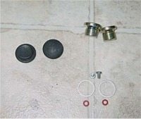
Parts Needed
You’ll need some parts to plug the holes.
Note that I’m not 100% certain about the BMW part numbers, but all of these parts should be available at your local BMW motorcycle dealer:
- Two timing hole plugs (BMW P/N 11 11 1 744 327);
- Two oil drain plugs (07 11 9 919 117);
- Two oil drain plug crush washers (07 11 9 963 252);
- Two screws for the vacuum take-offs under the carburetors (13 11 1 259 869);
- Two washers for the screws, (13 11 1 259 870).
If your dealer doesn’t have these parts in stock, they should certainly be able to order them from BMW. Sometimes these parts are sold in a kit called “air injection system” or similar. By the way, it’s my understanding that the screws have some type of special thread. Don’t try to use hardware store screws!
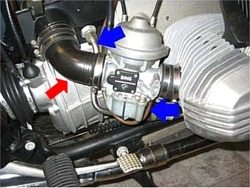
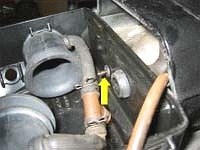
These two arrows point to the air injection lines similar to those on most post-1980 BMW R-series bikes.
The metal (silver) line goes underneath the head and injects air into the head through a fitting up under the exhaust pipe (below).
You’ll need a 19mm open-end wrench to remove the nut on the end of the tube where it goes into the airbox.
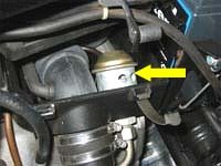
Use a 24mm open-end wrench (a 15/16 will fit and is what I used) to remove the nut that attaches the valve to the airbox.
This is the nut you can see in this photo that is closest to the airbox. After you remove the nuts, you can yank out the two valves fairly easily. After they’re out, insert the rubber timing hole plugs, one on each side of the airbox, to plug the holes.
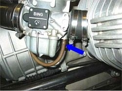
I ended up taking off the tube (red arrow) that runs from the carb to the airbox on the right hand side of the bike.
This gave me clearance to fit my fat 15/16″ wrench on to the nut that holds the valve to the airbox. I didn’t have to do this on the left hand side of the bike because there was enough clearance.
 |
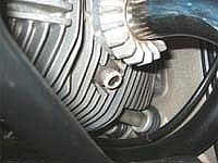 |
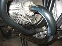
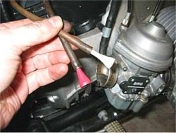
| Air injection tube going into head | Fitting for air injection tube |
 |
 |
| Left side valve | Right side valve |
These photos (left) illustrate the business end of the air injection tubes.
Remove the tube by loosening the nut that goes into the fitting (left photo).
Then remove the fitting itself; use a 22mm (or 7/8″) socket.
I was afraid these would be very hard to remove, but they actually were only hand tight, probably allowing more air into the head then was intended.
Remove the fitting and replace with the drain plug bolts. Don’t forget the crush washer!
I used blue Loctite, but Bob says no Loctite is necessary.
Next is the bottom set of photos on the left.
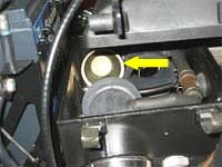
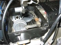
Looking inside the airbox, from the right side of the bike. These are the two valves (arrows) we’re going to eventually remove. Each one is attached to its respective metal air line as described.
Remove the hose from the vacuum takeoff underneath the carb (mine were brown but I think they replaced the original black ones).
The vacuum takeoffs have holes (one on each carb) are threaded. Plug the holes with the 2 screws. Don’t forget the washers!
The (brown on my bike) vacuum hoses feed into a “T” connection. You can’t see it — it’s in front of the airbox, down below where the arrow is pointing.
This is a very good time to check the water drain valve at the back bottom of the airbox.
The drain valve is rubber, and many of these bikes are 20 years old and it could have deteriorated. If it has, it provides yet another filter bypass for dirty air (thanks Kent!).
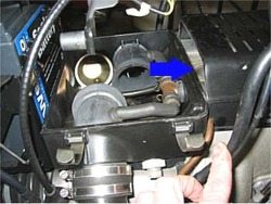
 Vacuum fitting
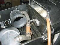 Vacuum fitting with plug
There’s a tube (not shown) that goes from the valves inside the airbox (not shown) to this fitting.
I cut a short section of that tube and plugged it with a golf tee coated in silicon adhesive sealant.
I decided to wrap the lines up and leave them in the compartment under the engine cover in front of the airbox.
It’s about impossible to get to the “T” fitting without further disassembly of the bike.
I figured they wouldn’t do any harm and someday I may need them again (perhaps to run a vacuum powered face shield wiper unit similar to the windshield wiper system on my old ’60’s Anglia?).
So I plugged the two lines with some golf tees stolen from my brother-in-law and made a neat little package which I tied up with some electrical tape and stuffed it in the compartment in front of the airbox.
Here’s the airbox with the valves taken out.
Make sure you leave the breather system as shown!
You can see the plugged hole on the far side of the box where the left-side valve used to go.
Make sure that all the holes are sealed up so that no dirty air can get into the airbox without first going through the air cleaner.
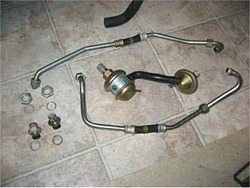
Here are all the parts you should end up with, minus the one narrow diameter vacuum hose that I cut up to plug the vacuum fitting inside the airbox.
This saves about a pound of weight also!
And finally, Kent Christensen also mentions the following:
“A sweet “finishing touch” to this project is to obtain the “Euro” airbox.
It is P/N 13 72 1 337 250 (the Pulse Air airbox is P/N 13 72 1 337 188).
The Euro Airbox doesn’t have any of the holes that need to be plugged in the USA version. This looks cool and there are never any worries about plugs falling out.
<GRIN>Guys even more anal will obtain the Euro engine top cover–no notches for the vacuum hoses–and cylinder heads without the threaded holes. Yeah, right.</GRIN>”.
Publication Date: 2003?
Owner Comments and Feedback
See details on submitting comments.