


The Talon T-3300 motorcycle alarm installed on a 2007 Kawasaki Versys.
Installing the system on other motorcycles may differ slightly, but the basic procedures should be similar.
Safety First
Prior to starting the work, the battery leads (negative first and then positive), are disconnected to allow the alarm system power leads to be installed without risking anything else electrical in the process.
With all components laid out on the workbench and after making sure the installation instructions were understood, and that desired additional items were at hand, the job can be started.
System Components
The Talon T-3300 basic motorcycle alarm kit consists of the following:
-
The main alarm module with its primary harness;
-
An installation kit with generic interconnect harness, power leads, mounting pads (tape and hook-n-loop) and mounting screws;
-
Siren (optional battery back-up component supplied);
-
Two miniature remotes;
-
Installation guide and user manual.
Three optional kits were also utilized:
-
Factory Connector kit, a “no-cut” model-specific kit with an interconnect harness for the signal lights and taillight. This kit also includes the Starter Kill Relay interconnect harness;
-
The perimeter sensor kit;
-
The battery back-up siren, identified above as part of the main system component listing.
While installation of the complete system can be accomplished with the supplied materials some additional items were utilized, all identified below.
Almost two months elapsed between when the main alarm module was test mounted under the seat area of the Versys and when this installation was finished. The system was ‘test-mounted’ for a couple of weeks to reveal any bugs, and when everything remained solid the installation was made more permanent.
Start to finish, total time taken was about four hours, including some initial testing and final configuration tests one sunny afternoon. Having the Versys interconnect harness saves at least half an hour, if not more.
The Talon system is definitely not the smallest. Those extra components all take up room so some location planning was needed. Thankfully the Versys has two storage areas that provide the space necessary to house system components. In the process however, the tool kit and any carried spares face relocation – not a big issue by any means.
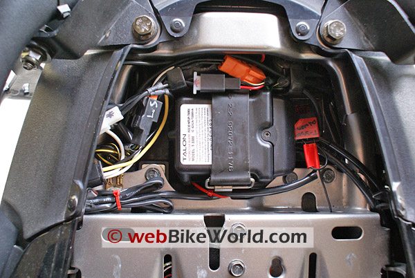
Talon T-3300 Main ModuleMain Module
The main alarm module and harness fits perfectly in the space between the rear tail-light assembly and the rear sub-frame crossover bracket. A matching piece of blue sleeping pad foam makes a perfect cushion for the unit.
The original Kawasaki-supplied rubber strap holds the module in place and allowing the whole assembly to be lifted up out of the way as needed.
As mounted, the module sits close to horizontal and the self-referencing technology in the tilt sensing mechanism overcomes the differential due to the angle caused by the side-stand. System documentation clearly states that optimal sensitivity is achieved when the control module is oriented so that it sits close to horizontal. Mounting the module on the side of anything is not recommended.
Talon T-3300 LED indicator mounted on Versys dash.LED Indicator
Tackling the small things first, the LED indicator was mounted in the right side of the Versys dash – a matte black plastic shroud surrounding the instrumentation cluster. Selecting a spot just to the right of the LCD display, a small 9/32 hole is drilled through the shroud and when inserted through the cleaned out hole, the LED sits about 1mm above the surface of the dash.
With this placement the bright LED is clearly visible from the rear or side of the motorcycle. To create a frame for the LED and a more professional look, a thin-wall rubber grommet is inserted in the hole and then the LED housing glued to the underside of the dash.
The wire lead itself is run under the right hand fairing panel (pressure tape cable holders and small tie straps) and then inside the frame tube of the Versys to the battery box area, where it can await connection to the main module harness.
Main Power
Stealth Harness – all of the harness leads are black, which can be confusing. Even though the main power lead is fused and marked (+) close to the module, it is best to mark the main power lead with some red tape or something to more clearly identify its purpose. Accordingly, both the power lead and the fuse holder were marked in this fashion.
Rather than using the lightweight wire lugs supplied with the kit, slightly heavier duty ring terminal replacements were substituted. The Positive and Negative wire leads can be run through the Red and Black plastic caps used to cover the battery terminals. This makes for a cleaner installation, and in the case of the negative terminal a good thing – the terminal is very close to a cross-frame component.
Before soldering the leads to the terminals, silicon heat shrink was cut and slide over the wires. Once the soldered connections had cooled down somewhat the shrink is activated with a handy dandy heat gun…so much better than matches, a lighter or, a blow-torch (I’ve seen it used, believe it or not! Don’t use anything with an open flame anywhere near the fuel tank!). While a bit of overkill, the silicon provides an absolute waterproof seal and strengthens the whole connection.
Switched Power and Indicators
Once the main power and ground leads ready to go, the next set of connections can be tackled – the tail light and the signal lights.
The tail light connection provides a switched 12V Positive connection when the ignition is turned on. The turn signals are wired to the alarm system to serve as a prominent visual interface, along with the LED.
Without the optional Factory Connector Kit, the procedure is still straight forward although a little more cutting and splicing effort is needed. The supplied Universal Connector has four wires – two White for the signal lights, one Yellow for the tail-light and a Black lead that provides a common Ground.
Using Table 1 in the Installation Guide, the ‘hot’ or Positive side is easily identified from the stock wiring connectors that reside next to the taillight housing and as such, easily accessed. Note – when in doubt, the ‘hot’ side should always be verified.
On the Versys, the Green and Grey wires of the Left and Right turn signals respectively are the ‘hot’ wires. A splice is needed into each and the simplest method is to use in-line connectors. In any case, the splices need to be as secure as possible and either sealed with heat shrink or taped up.
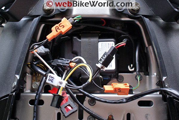
Using the Factory Connector Kit specific to the Versys this task is even simpler – no splicing is needed whatsoever. The kit consists of an 18 AWG harness with two Orange connectors for the signal lights and one White connector for the taillight, all terminating to a Black four-pin connector.
This harness is interconnected into the original wiring connectors and takes only a couple of minutes at most. The wiring bundle can be secured to the right of the taillight housing and/or inside the right side rear tail section. Given the direct interconnects made no separate ground lead is needed or provided with this harness.
The Talon Factory Connect harness specific to the Kawasaki Versys.Immobilizer – Starter Kill Relay
The most time-consuming activity during the installation is in wiring up the Starter Kill Relay, which provides the Immobilizer function. Once the main fuse assembly is found (Shop Manual = Good) and accessed, the remaining steps are pretty simple.
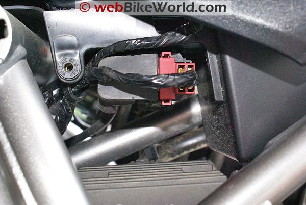
The alarm relay has a sturdy four-point connector. Two of the sockets are already used for another system harness that terminates in a small three-pin connector, for eventual connection to the main module harness.
The other two slots are reserved for the second interconnect harness provided with the Factory Connection Kit. This tailored two-wire harness has an empty white connector and single female spade receptacle on one end and two female spade receptacles on the other end. It is used to make the necessary interconnection with the main starter relay circuit for immobilizer function purposes.

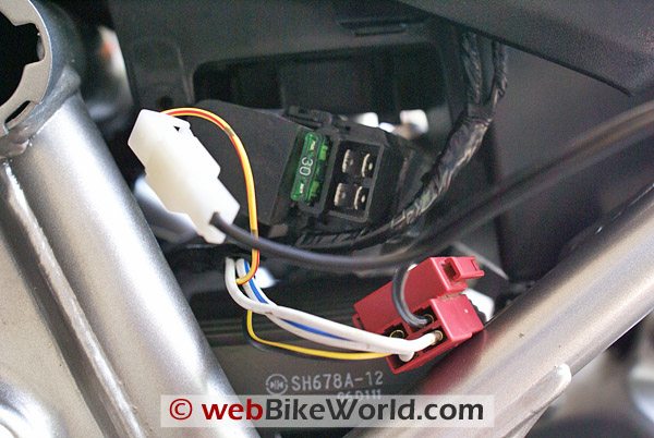
On the Versys, the main starter lead is found as part of the main fuse (30A) assembly located on the left hand side of the motorcycle, housed in a plastic box assembly, just above the regulator/rectifier unit (finned unit generally exposed to the elements).
Remove the left side plastic frame cover and the small plastic cover plate to access the main fuse assembly. Pull the rubber and plastic assembly gently out of its housing and then disconnect the red plastic integrated fuse cover and starter relay plug. This will expose the main 30A fuse socket and the starter terminal.
With the integrated fuse cover and starter relay plug in hand, peel the wire back to reveal the target, the Yellow with Red stripe wire. Now comes the fun part…being careful and using a very small flat blade jeweler’s screwdriver, remove the Yellow with Red connector from the starter relay connector.
The Yellow with Red connector is inserted into the blank spot on the plastic white connector of the interconnect harness and the single black wire spade receptacle of the interconnect harness is inserted into the just vacated slot in the Versys starter relay connector.
If the Factory Connection Kit is not used, the Yellow with Red wire needs to be cut, usually an inch or two back from the connector and the supplied two wire black harness used. One wire of this harness is spliced to each cut end of the Yellow with Red wire.
With the necessary wiring changes completed, the red plastic assembly is plugged back into its socket. Route the interconnect harness up between the frame tubes and the battery box to the under-seat area and then plug the two spade receptacles into the vacant slots of the four point relay connector (these slots are not specific or coded in any way).
Note – make sure all the starter relay modifications are absolutely solid and sealed. If this connection ever fails, the motorcycle will not start. Even though the interconnect harness is pretty much plug-n-play and concealable, all connections were taped.
The alarm relay itself nestles securely into a stock cut-out in the front wall of the main plastic tray, next to the battery. This spot works well for two main reasons: ease of access and, to accommodate a length shortfall in the main starter relay interconnect harness.
Piezo Siren
The piezo siren, fitted with the optional battery backup, is up next. Conveniently the thin middle storage area provides a snug fit – some cushion tape keeps the component isolated from surrounding surfaces while the tray strap keeps the noise-maker in place.
Before connecting the siren lead to the main module harness, make sure the piezo alarm is turned on. Using one of the two supplied keys, switch the lock from the Red dimple (Off) to the Green dimple (On).
Perimeter Sensor
Some ad-hoc tests reveal that one of the recommended mounting points, on top of the battery, provides a good mounting spot for the small plastic perimeter sensor module. Alternate locations inside the left rear side panel and next to the alarm module itself were tried, but the battery position provided the best sensitivity overall.
Talon T-3300 final installation.Visibility and Security
In its original orientation, the alarm module leads were going to be a tad short. By simply turning the module 180 degrees which put the harness to the left of the motorcycle all leads would reach.
For the ‘permanent’ installation, the wire leads are all run from the main module, around the outside of the seat-lock assembly and then down along the frame in to the main tray area. All leads are secured directly to the frame or to the plastic tray by pressure-tape cable mounts. With this done, everything is out of the way and with the side panel and seat installed, out of sight.
Testing
At this stage, with all work checked once more, power can be applied. With the positive lead and then the negative leads reconnected, the alarm will give an initial power-up warning chirp – this thing is loud!
At this stage the system remotes can be tested for basic functionality and then to configure the system to the desired settings. It is a good idea to work through the Transmitter Summary Table and the Main Functions sections of the manual. It is time well spent in getting familiar with this versatile system and to verify that the installation was complete.
More: Talon T-3300 Review: Part 1
Owner Comments and Feedback
See details on submitting comments.