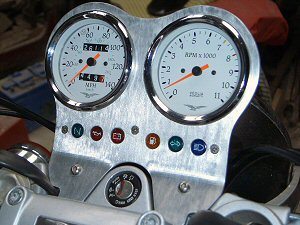
Reading the webBikeWorld technical article about fitting a tachometer to a Moto Guzzi ‘Jackal’ got the old brain cells whirring.
Since buying my Jackal I had really missed the benefits of a tacho and as it was my first Guzzi, I could only go by the sound and feel of the engine to tell me whether or not it was happy with the revs I was using during changing up or down the box – I did not have a clue as to what those revs actually were.
OK, I wasn’t doing clutchless racing changes all over the place, and my lap times to the local bikers meet were not really a consideration, but still, I was determined to fit a tachometer to see what was going on in the noisy bit. I also really wanted an analogue clock for use when touring (I was late a couple of times last year when touring in the wilds of N.W. Scotland and missed a couple of closing times which led to all sorts of grief) but that’s a different story.
After reading the article, I talked both to Martin at MotoworksPete Morecambe at Reboot Guzzi Spares to see what was available in the way of second-hand tachometers. I also examined the drawings in the Guzzi manual.
I suppose I could have bought either a new or second-hand Cali EV dash but they don’t seem to be all that easy to get hold of and I had made up my mind to see what I could produce in the way of a new dashboard myself (I am often accused of doing everything the hard way). I also wanted to try and keep the horizontal layout of the original warning light cluster, in preference to the Cali EV version.
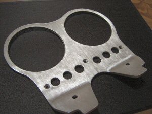
The original Jackal item is stamped out of 4mm alloy plate and the edge finish is pretty poor – surely I could improve on that at least?
Well, in the end, it came out not too shabby and I’m quite happy with it. The making of the thing was only the half of it however; obtaining the right tachometer (I wanted one that matched the speedometer), the cabling, the wiring loom etc were the other half and I will tell you what I found out and the odd problems I encountered along the way.
Materials
I could not determine what type of alloy was used by Moto Guzzi for the original 4mm thick Jackal dashboard but experience told me that most aluminium alloys would probably do the job by using a bit of care during manufacture. As for stresses on the dash, these would be pretty minimal.
For the technically-minded among you, the material I made mine from was a bit of 4mm thick 1050-H14 aluminium (BS 1470). This is a 99.5% pure aluminium, which is malleable and has good corrosion resistance. You can get a table, which will convert BS (British Standards) to ASTM (American Society for Testing Materials) if you need to.
Don’t worry if you do not have this material available; just use what you can get. As long as you can pull a bend on the mounting ‘Lugs’ without it cracking, then it will probably be fine. Aluminium comes in various grades of hardness: fully soft, half-hard and fully hard. I don’t have a clue what grade the bit I got was. I just made a test piece, put it in the vice, and it bent OK (fine, we’ll use that then).
Manufacturing Methods and Tools
This section may seem to be too early in the proceedings but how you intend to manufacture the dash has a bearing on everything else.
Water Jet Cutting
I originally intended to have my dash cut out by the water jet cutting process and found a local company that does it. As with anything, start-up costs are the killer but this particular company makes aerospace bits and is used to one-offs thus keeping it fairly economical. Enough orders and it would be worth having a batch done.
I talked to the Managing Director about composite cutting and PU / PE plastics and he showed me some samples that were beautifully done with a splendid finish cut directly from CAD via Laser. Very nice. This got me going I can tell you! Look for local firms – it’s amazing what you can find on your doorstep although it can be a bit of a Sherlock Holmes job.
If you get stuck, take the original dash to the company that does the water jetting and ask if they will use it as a template for the warning light cluster holes PCD (Pitch Centre Diameter) and the mounting holes and explain to them via a sketch what you want & where you it. The company I spoke to were quite happy to produce a CAD (Computer Aided Drafting) manufacturing drawings from my description.
Plasma Cutting
This is not a bad way to do it if you can’t be bothered to cut out the profile yourself. Bear in mind though, that it will leave a relatively rough edge which you will need to finish off yourself using files, linisher, sander, flapwheels, whatever. You could extend the process to cutting out the 85mm (diameter) holes for the instruments but once again, you will need to finish the edges of the cut by hand and there are much better ways of cutting these two large holes.
Laser Cutting
I looked at this method but rejected it in favour of water jet cutting. This was only my personal preference and there is nothing that says you can’t use it yourself.
CNC Milling
Possible and feasible if you own, or have access to the right bits of kit. I don’t and haven’t so this one went out the window from the off.
Produce it Yourself
And who said today was going to be boring?
Tools
To cut it out yourself you need some basic hand tools and a drill. If you have a small bandsaw, so much the better. If you don’t have a bandsaw, use a hacksaw but wear some Wellies to catch the sweat.
I was given a little Black & Decker bandsaw which must be about 300 years old. The blade is fairly coarse at 10 tpi (teeth per inch) and I am sure it is a wood, rather than metal, cutting blade, however, I took my time and didn’t force it when cutting out the profile, and it did the job beautifully. A good tip here is to drill a hole at each corner for when a line changes direction; this will allow you to rotate the dash and stop the blade snagging.
To cut the 85mm diameter holes (or 3.346” in old money), go out & buy a hole cutter if you don’t already have one.
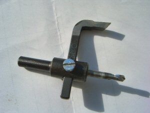
The cutter I used is what I have always known as a ‘trepanning’ tool – they call them ‘Tank Cutters’ nowadays in the UK (see photo left).
It is infinitely adjustable and can be used for all sorts of other stuff. It cost about £8, so it won’t break the bank and gives not a bad finish with a little tweaking here and there.
A hole saw gives the best cut; however, I couldn’t get one anywhere in 85mm.
A couple of medium / fine flap wheels are needed, both for finishing off the edges (although I used files and wet & dry paper) and for doing the brushed satin finish.
A few files, a bit of wet & dry sandpaper, a couple of drills and a countersinker for the warning light cluster / mounting screw holes and that’s about it really.
Manufacture
Drawings
I produced the drawing as I originally intended to use water jet cutting. As it happens, it came in handy anyway. The only dimensions that are fairly critical are the holes for the warning light cluster (including the 3 x off countersunk holes for the screws that retain the cluster to the dash). The remainder of the dimensions have some tolerance, and you can make adjustments to the fit. The bend line also has a bit of tolerance.
 |
 |
 |
| View 650×488 Photograph of Finished Dashboard | View 578×360 CAD Drawing of Dashboard | Download .zip File With Dashboard CAD Drawing* |
| *Note: .zip CAD drawing file includes .DXF, .DWG, .SKF and .GIF formatted versions of the CAD drawing. | ||
Handling The Material
You won’t get a good brushed finish if at the end of machining / cutting out, your dash is covered in scratches, gouges and dents. Aluminium normally comes with a translucent cling film type of covering – remove it from one side and cover it with masking tape. This will protect the finish and give you a good surface to do your marking-out on with a very sharp pencil. You can centre-pop the holes through the masking tape and you only need to totally remove it when you have finished the machining / cutting out.
Marking Out
See the drawing for the dimensions. If you do not like the shape, tweak it to suit yourself.
You have a couple of options here; either mark out the shape on the masking tape using pencil, compass and scribers or print-out a full size copy of the drawing and use it as a template to transfer the outline shape to the plate.
Probably more accurate to mark out all the hole centres onto the masking tape and then use a template to mark-out the outline.
You should be able to see the rolling direction of the plate; make sure the ‘grain’ of your dash runs fore and aft as this will help give you a better finish.
I used the original dash as a template and drew the whole thing out on the piece of Aluminium. I then drew a horizontal line through the hole centre and used this as the horizontal centre line for the twin holes, spacing their vertical centre lines far enough apart to leave about 5/8” of material between them (at the centre).
I then drew a line parallel with the circumference of these two holes, to allow about 5/16” of material around the holes, and using a French curve, drew a smooth radius to blend the lines into each other.
Cutting Out
The sequence I used to make it was as follows:
-
Mark out the plate, including profile and hole centres
-
Centre-pop all of the hole centres
-
When you have the hole centres marked-out, centre-pop them using sharp centre-pop. A light tap should do it in a material as soft as this – you don’t need / want them too deep.
-
Pilot drill each hole centre using something like a 1/16th drill
-
Cut the 85mm holes
-
Use the trepanner / tank cutter or an 85mm hole saw if you can get one.
-
Drill the warning light and mounting holes. De-burr.
I finished off the warning light holes in the top face of the dash using a bit of wet & dry as I wanted a really clean edge to the holes. For the underside of the dash, I just used a large drill, rotated by hand. When you have completed this operation, do a trial fit of the warning light cluster. I had to relieve one hole slightly with a round file to get the warning light cluster to fit snugly but this only took a couple of light strokes and in she went.
-
Cut out the profile using a hacksaw / bandsaw / plasma cutter
-
I used the bandsaw and it gave a really good edge.
-
Smooth off and finish off the edges
-
File, wet & dry, wire wool, flap wheel can all be used to remove cutting marks and give a nice, neat, smooth edge.
-
Bend the ‘mounting lugs’ to the correct angle using the original dash as a pattern
Get two pieces of a hardish wood, such as Beech – make sure they are smooth. Clamp the dash in a vice between the pieces of wood to prevent marking the Aluminium with the vice jaws. Line it up for where you want the bend to be using the original dash as a template, and bend to the correct angle.
I placed a piece of wood behind the dash and gave it a whack with a wooden mallet, checked it against the original dash, then gave it a few more whacks until it was at the correct angle. Precision stuff really.
Surface Finish
When you have the ‘mounting lugs’ bent, finish off the dash with a flap wheel. I used a flap wheel in a pistol drill set at drilling speed (i.e.: not too fast) and didn’t apply too much pressure. Find a scrap piece of Aluminium to practice on and you will soon get the idea.
As I was working on my own, I clamped the dash to a bench (put wood under the clamp to prevent marking the Aluminium). Better to press-gang a volunteer if you can.
Holding the drill with both hands, and starting at one side, I ran the flap wheel down the dash in one smooth and even stroke. This will give you a ‘stripe’ of satin brushed finish. I repeated the strokes until I had completed the surface finish.
There are other finishing options if you don’t fancy doing it this way. Depending on what is available in your locality, paper blasting, anodizing, etc. are all good methods of obtaining a professional looking finish you can be proud of. I think a brushed finish, which is then anodized would make a fine job and depending on the colour of your bike, you could be really creative here.
Finishing-Off
Get some Methylated Spirit and de-grease the dash, trying not to leave any finger marks which show up easily on Aluminium. Spray with a few coats of acrylic lacquer.
I got a can from a car accessory shop which did the job perfectly. I allowed the spray can to reach room temperature, warmed the dash a little, then gave the edges only a couple of light coats.
When these were dry (about 15 minutes) I then lay it flat and sprayed first one, then the other, side of the dash with a few coats until I was happy with the finish. I left it overnight before any subsequent handling, then gave it a gentle ‘T’ Cut and wax.
Fitting and Connections
Cables
The speedo cable fits fine.
Wiring
The wBW article “Moto Guzzi Jackal Tachometer Installation” should give you plenty of information on how to wire things up.
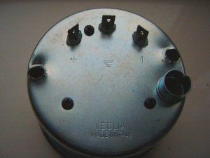
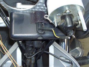
In addition to the instrument bulb holder, the rear of the tacho has 3 x off spade terminals (see photo, left); a +ve, an earth and a spade marked ‘1’, this latter being the connector for the feed from the ECU to power the tacho.
For instrument lights, I took a tapping from both the +ve wire that powers the speedo instrument light and the -ve earth wire where they connect to the speedo. That way, the joints are inside the speedo cover.
I made up two wires; one with spades (+ve instrument lights) and one with a ring terminal one end and a spade at the other (-ve instrument earth).
The other wiring you need is for the feed to the tacho itself from the ECU. The jackal is pre-wired for a tacho as shown in the circuit diagram in Section P, Page 16 of the Guzzi manual. (I assume this is what ‘Predisp.’) means.
‘All’ you need to do then, is to find the “10-way A Pakard connector (dashboard)” and trace the pre-wired socket. Easy, no?
Have a poke around the front of the bike (technically speaking) when you have removed the old dash and you will find it.
Fitting the Dash
-
It should bolt straight on to the bike if you have drilled the holes correctly. I fitted things in the following sequence:
-
Find the pre-wired tacho plug. Make up the jumper wires. Sort out the wiring.
-
Fit the dash
-
Fit the warning light cluster
-
Fit the speedo. Attach the wires to the instrument light and earth. Cover the hole at the top of the warning light cluster. I warmed things up with a hairdryer and covered it with some black, super sticky tape (it was actually Velcro) making sure it was well stuck down to prevent any water ingress. I wasn’t too worried as I have a screen fitted. Don’t attach the speedo cable or cover just yet.
-
Fit the tacho. Attach the jumper wires to the instrument light and earth. Attach the wires to the spade fittings at the rear of the tacho unit. Fit the speedo cable. Attach the chromed speedo / tacho covers.
-
If you have a screen, re-attach. You may find, as I did, that you will need to have slightly longer spacers so that the screen does not come into contact with the instrument covers. In my case, I fitted 3 x off stainless washers which were sufficient to give ample clearance between screen & covers.
-
That’s it really.
End Stuff
If you get stuck, I will help where I can. E-mail me at vsheron@clara.co.uk . If you do send an e-mail, please make sure you put a relevant and descriptive title in the subject box – if I don’t recognize the sender or the subject of an e-mail, I delete it at the server without reading it due to the sheer number of viruses flying around. Replies may take a couple of days.
Suppliers & Data Sources
Engineering suppliers for most of the various bits of kit. Material stockists for the Aluminium. Car accessory shops for wet & dry.
Note: For informational use only. All material and photographs are Copyright © webWorld International, LLC – 2000-2011. All rights reserved. See the webBikeWorld® Site Info page. NOTE: Product specifications, features and details may change or differ from our descriptions. Always check before purchasing. Read the Terms and Conditions!