This section describes typical installations for the Dispatch 1 system.
I will use the BMW F 800 GS test mule and my new 2010 R 1200 RT that joined the family fleet last summer as examples.
Installation Notes
While the Dispatch 1 power management system will find some permanency on my 2010 BMW R 1200 RT, the first host platform ended up being the trusty F 800 GS test mule.
It was once again taken down to Florida for some December R&R (riding and relaxation).
For both installations, the controller module will be mounted on the handlebars and while I hoped the distribution module would fit under the seat of both motorcycles, this location is only possible on the R 1200 RT.
It has the real estate available, whereas F 650 GS and F 800 GS owners will know these versatile machines have limited space under the dummy panel and less under the seat.
I took the Dispatch 1 system to a few dealers to check fitment and outside of some off-road and pure-sport machines, the power distribution module component should be able to fit or be carried somewhere on a wide range of motorcycles.
The controller module can be mounted up front or carried in a tank-bag or a pocket on just about any bike.
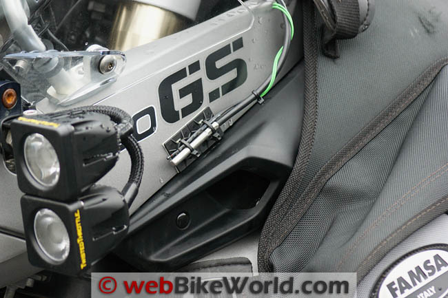
The Dispatch 1 temperature sensor mounted on the BMW F 800 GS.Installing the Dispatch 1 System on a 2009 BMW F 800 GS
1. Installing the Power Distribution Module
I really thought the back cavity on the F 800 GS, where the optional BMW alarm system normally resides, would be able to house the Dispatch 1 power distribution module.
But while the harness and connections could be accommodated, there just isn’t enough clearance for the seat hooks to engage without putting undue pressure on the module.
If the optional alarm system is mounted, then this space is not available anyway.
Another potential F 800 GS location for the distribution module is inside the top leading edge of the left or right side panel, but that is something for another day and another distribution module kit.
So the expedient solution was to just house the distribution module in my Famsa tank bag and use the provided protective bag if needed.
My decision then made, the Famsa tank panniers and tank bag were removed, followed by a two-day-old but already extremely comfortable Sargent World Sport Performance Enduro Seat.
The top dummy panel was next, secured via six Torx screws.
This reveals the current accessory wiring maze — it is neat but tightly packed, something that the Dispatch 1 will help resolve.
As I had already installed everything to allow (relatively) quick access to the airbox cover for maintenance, it didn’t take long to disconnect the wiring from my current Centech auxiliary fuse panel and remove it, along with its relay and power harness.
This left two relay and harness assemblies for my LED light systems, two accessory leads and a power lead for my Garmin zumo 665.
Admittedly the Centech panel could have been left in place, but I made a conscious decision to remove it for this installation.
If the Dispatch 1 works as advertised it will completely replace the Centech anyway, which has been and will remain an ultra-reliable and versatile device.
With the distribution module getting accustomed to its new digs, I realized the long leads trailing from the distribution module were really going to facilitate installation.
The main red and black 10AWG power wires on the Dispatch 1 power distribution module are 29 inches (74 cm) long and the yellow 16AWG trigger wire is 57 inches (145 cm) long.
The thin green wire that terminates in the probe that senses the ambient temperature for display on the controller module is also 29 inche (74 cm) in length.
After disconnecting the battery leads (negative first, then positive) and with everything safely secured out of the way, the first wire I connected from the Dispatch 1 power distribution module is the yellow trigger wire.
I used a red PL1824 (18-24 gauge) Posi-Lock connector to mate this wire to the thinner switched lead used for the just-removed distribution component.
This wire originates under the seat, where it is connected to the green/blue striped wire of the original equipment BMW Diagnostic Plug (the round component with twist cap) harness, using a small PTA2022 (20-22 gauge) Posi-Tap connector.
I actually had two trigger wires running off this Posi-Tap; the second one was used for the twoDenali LED light kits, but it was no longer needed after installing the Dispatch 1.
Note: Using “any old hot wire” for a trigger is not typically the best solution for a CAN-Bus system.
Alternatives for BMW owners are to use switched power available from the accessory connector located on top of the battery (Repair Connector kit, BMW PN 80 00 0 611 656 makes this easy); a third-party City Light Adapter harness; or by tapping into the taillight/license plate wire.
Next I connected the Dispatch 1 power distribution module to the positive and negative battery lead connections of the motorcycle.
For best operation, my Scottoiler eSystem (review) was left connected directly to the battery, but everything else that was removed from the Centech is going to be powered and managed by the Dispatch 1 system.
I bundled the thin green ambient temperature sensor wire from the Dispatch 1 is with the red and black power wire and the yellow trigger wires, then routed this to the left forward edge of the battery compartment so it would clear the dummy panel once that was reinstalled.
I wrapped the Dispatch 1 sensor wire around the external sensor lead of the Booster Plug (review)and slipped both sensor tips into the small tie-strap cradles secured to the left side panel above the intake snorkel.
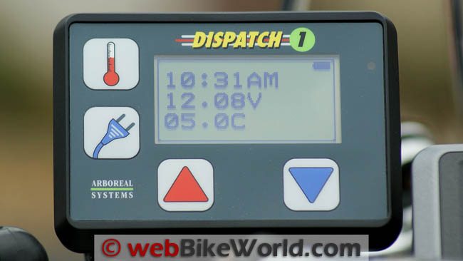
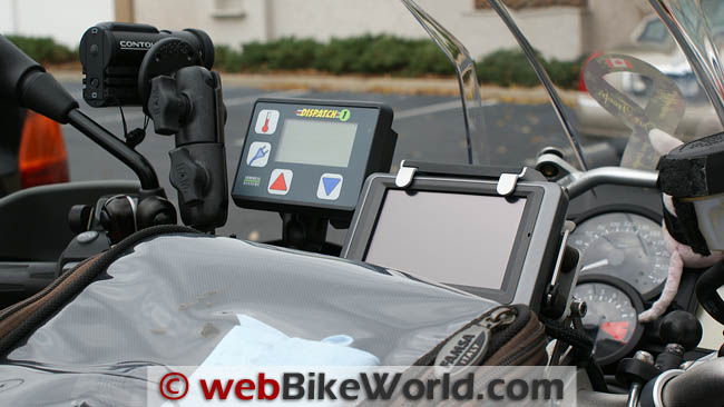
The default “environmental” screen of the Dispatch 1 control module.2. Installing the Dispatch 1 Controller Module
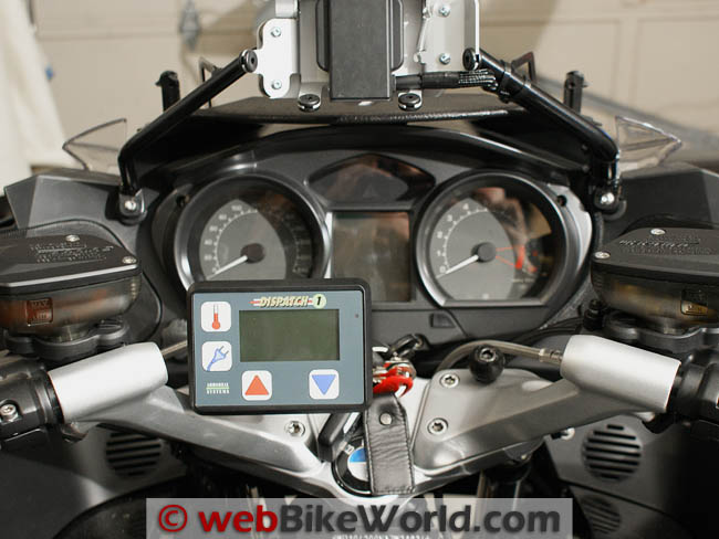
I used a RAM diamond mounting plate (RAM-B-238U) and ball head to mount the Dispatch 1 controller on the handlebars.
I fastened the RAM mount to the back of the Dispatch 1 controller unit via two Phillips-head mounting screws with medium thread locking compound.
The controller module is joined to an existing RAM U-mount by using a short 1.75 inch arm (RAM-B-201) on the left side of the already-crowded handlebars.
I left it here for a couple of days before moving it to the right side of the bars so that a new GPS unit under evaluation could be mounted on the left side.
Outside of actually turning on the ignition and initializing the system via the control module, the installation on the F 800 GS was now complete.
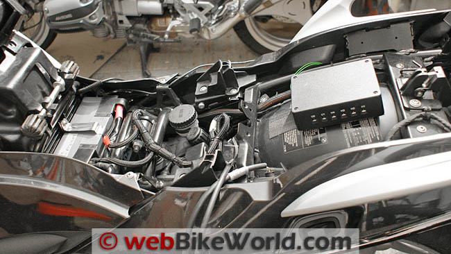
The Dispatch 1 power distribution module mounted remotely in the BMW R 1200 RT.Installing the Dispatch 1 System on a 2010 BMW R 1200 RT
After reluctantly completing the drive back north early in January (and in some pretty bad weather at times), the Dispatch 1 system was removed from the F 800 GS test mule for some more photos before it went back out to the garage to get familiar with its new host, the R 1200 RT.
The plan, hopefully completed before March and Daytona, includes getting weatherproof co-axial and USB power port components, mounting them in strategic locations on the RT and connecting them all to the Dispatch 1.
With the power port pieces and other goodies on their way to me, getting the system installed becomes more urgent.
I also wanted to get this submission on its way to the Editor.
With the seat sections put up on the shelf and the tank rail frame removed, along with some of the fairing sections, all to facilitate the running of leads, it was time to get the Dispatch 1 power distribution module installed under the seat on the back fender section of the R 1200 RT.
As per the F 800 GS installation, the switched wire on the BMW Diagnostic Plug will serve as the “trigger” power for the Dispatch 1 system.
While the Diagnostic Plug is easily to access on the F 800 GS, it is less so on the RT, so much so that I wonder why the same easy access mounting could not have been used on the RT?
To get direct access to the bottom of the Plug, it is necessary to remove two small (T-15) M4 x 10 mm sheet screws.
These are located on the left and right side of the plastic housing and then lift the housing up and forward, revealing the bottom of the Plug and another relay.
The desired wire for tapping into this power source is the same as for the F 800 GS — a thin green/blue striped wire located on the No. 10 pin receptacle as marked on the bottom of the plug.
As this wire is powered on and off with the ignition switch, it makes a perfect “trigger” for a number of things without having to intrude upon any other part of the BMW CANBus harness.
I initially thought my supply of the grey 20-22 AWG Posi-Taps was depleted, but after an intense search, two of the precious items were found — time for a resupply from the wBW store.
With the trigger wire slipped up into the piercing cap and the Posi-Tap screwed onto it, the yellow trigger lead from the Dispatch 1 distribution module is screwed into the other half.
Next, I disconnected the battery — negative lead first, then the positive and both were secured, away from the terminals and other components. Before doing anything else, I removed the Garmin 665 power leads from the connection mix.
The Garmin power lead was then attached to the switched (time-delay) BMW accessory plug located inside the front of the fairing.
To keep the Dispatch 1 distribution module secured on the back rise of the rear fender of the bike, a rectangular panel of thick industrial strength Velcro was used because it provides easy removal and some cushioning for the module.
A short length of half-inch (13 mm) Flexo F6 split braided sleeve was added to protect the three leads from the distribution module to just behind the battery.
From which point they each go their separate way nestled inside individual lengths of quarter-inch (6mm) Flexo for protection and appearances.
The green sensor lead was tucked through a rear side frame component and secured to the outer plastic carrier molding on the right side with a small translucent cable clip, leaving it out of the way, out of sight and functional.
As a connectivity test, the red positive wire and black negative leads from the distribution module were secured to their respective terminals along with the battery leads and everything tightened back up.
With the ignition switched on, the controller module was powered up and three seconds later a radio link was made with the distribution module.
The default Dispatch 1 controller module screen then appears, displaying the correct time, a voltage reading and a temperature reading (13.4C in the garage under the lights…toasty).
From this point, I tidied up the wiring with large and small nylon cable ties applied at strategic spots to keep the leads nestled down in place while still allowing a bit of flex.
I left about three inches of play at the distribution module end in case it needs to be adjusted slightly when the rear section of the seat is installed.
After a few more photos of everything nestled under the seat, a final connectivity test was done using the controller module to activate the switched UN1 port and I tested its output at the leads, with a reading of 12.22V present on the circuit — good stuff.
Dispatch 1 Overall System Observations
Port Connections: The co-axial power ports on the Dispatch 1 power distribution module are recessed, but the shape of the cutouts doesn’t match well with the shape of the co-axial plug housing on the cable.
A good connection is made but if the module is hit or moved around, the plugs can pull out.
Since the distribution module needs to be kept dry, in this regard I think that a flush-mount approach would work for a tighter fit and, if a weatherproof assembly is used, then it should provide a better seal to increase resistance to the elements.
Port Identification: Another minor observation is the use of different designations for the ports between the information displayed on the Dispatch 1 controller module screens and what is marked on the the distribution module.
The USB ports on the distribution module are marked USB1, USB2 and USB3, while the operational screen display shows U1, U2 and U3. I suggest the labeling should be made consistent.
Similarly, the switched ports are marked U1 and U2 on the power distribution module but UN2 and UN1 on the controller screen. Acknowledging the use of short-form designators and acronyms for markings, standardization is the game; these differences could result in some confusion for new or casual users of the system.
Documentation: From an information and instructional perspective, the Dispatch 1 Owner’s Guide is basic.
And while it contains the essential elements of information needed for the most part, there are a couple of missing procedural steps and some prior knowledge of terminology and procedures is assumed.
Reading through the manual once or twice, and then stepping through it all again with both the controller and the manual will be valuable.
The manual is also available from the website as a PDF file, along with a very useful Addendum sheet that rolls up the latest software changes and details configuration or procedural changes.
System Updates: At this point in time, system software updates can only be performed by returning the complete system to Arboreal Systems.
The ideal, of course, would be the ability to send out or post updates on the website, something I firmly believe will come to pass.
The Dispatch 1 System: Final Conclusion
You have probably already deduced, from both parts of this posting, that I am really impressed with the Dispatch 1 system.
The system is more complex, and expensive, than a simple distribution device, but then it does a lot more as well, and it has portability aspects built in.
The wireless link connecting the two modules provides great range — I can walk over a block away from the garage and still successfully manage the system and everything connected to it.
And staying with portability, for multi-motorcycle owners, like myself, acquiring and installing additional Distribution modules (set for a common PAN ID) puts the required distribution component on those machines, while a single Dispatch 1 controller module can be easily moved between motorcycles with the rider.
Can we say cost effective?
Another sign of efficiencies…I have been able to remove close to fifty or sixty feet of wiring so far from the bikes, along with four relays and three switches.
The inside of the dummy panel no longer looks like a tidy disaster waiting to happen and even my handlebars are less cluttered (kind of).
Some will see it as a matter of putting “all the power management eggs in one basket”, whereas I view it as a clever implementation of requirements using proven technology. Eggs aren’t as fragile as they seem…
The Arboreal Systems plan is to grow the Dispatch 1 product by adding even more functionality in the future and it obviously has the architecture and power to act as a distribution and management hub for more than just accessory power.
The ability to interface with and present data collected by modern motorcycle sensors is one capability that comes to mind…
Late Breaking News
Arboreal Systems has informed webBikeWorld that they are beta testing three new features, which they expect to release in a week or so.
As always, software upgrades are free…but at this point they have to be done at Aboreal Systems (in Berkeley, California).
The new features include:
- The ability to now utilize the variable/modulated H1 through H4 circuits for light modulation or light dimming if desired.
- The ability to designate any combination of the four variable H1 to H4 outputs as switched outputs.In this mode, a single press of the Up or Down button will toggle the “thermometer” to either full on or full off — very handy if you want to use any of these circuits for switching (i.e., they will now be able to function just like the two high-output UN1 and UN2 circuits).
- The ability to designate any combination of the ten ports to be shut down after the motorcycle is shut down based on time, with an available time range of between one to 120 minutes.As a fail-safe, this feature runs in parallel with the existing voltage level alarm-dependent auto shutdown, so irrespective of the time-based shutdown setting, if system voltage drops to one volt under the alarm level, the system will shut down.
We have coordinated with Arboreal Systems to send the evaluation system back to Berkeley for the latest software updates. Stay tuned for more on the latest system changes.
NOTE: Feedback, comments and the product information summary table are located in Part 1: Overview
System
- Management: Microprocessors control all functions including heat outputs that are adjustable over 32 linear steps.
- Protection: Distribution module has fuses and protection circuits.
- Radio: State of the art ZigBee radio modules, minimizes power and optimizes range:
- Wireless ZigBee radio links controller and distribution modules.
- Single controller can be used for multiple distribution modules.
- System Draw: Depending on trigger/circuit configuration, draw is between 280 uA and 26 mA.
Environmental Data Displayed
- Time, date and day.
- Motorcycle battery voltage.
- Ambient air temperature.
Controlled Outputs
- Four heated garment circuits.
- Two switched output circuits.
- Three smart USB power circuits.
- One RJ11 power output for radar detectors.
Controller Module
- Switches: Expected life cycle of ~1,000,000 cycles.
- Front panel: Completely waterproof and UV protected.
- LDC panel: Transflective, backlit and polarized.
- Ambient light sensor: Intelligent backlighting control.
- Mounting: Metal bosses for RAM mounting system built in (RAM-B-238U).
- Sealing: Silicone O-ring.
- Battery Life: Stated as ‘exceptional’ due to use of four AA cells and power management.
- Dimensions: 4.25 Wide x 3.125 Tall x 1.25 Deep (inches).
Power Distribution Module
- Capacity: 750 Watts @ 12VDC (60A).
- Flexible allocation from 5A to 15A per circuit.
- Heating outputs: Four high-efficiency phase width modulated variable output circuits rated at 10A each (at full power setting these can be used as additional switched 12V circuits).
- USB outputs: Three microprocessor-controlled smart power over USB.
- RJ11 output: Suitable for Valentine and Escort radar detectors.
- High Current Outputs: Two 10 Amp outputs suitable for auxiliary lighting, etc.
- Fuses: Eight automotive spade-type mini fuses, accessed by removing distribution module cover. Recommended replacement fuses are: Heating circuits: 6 to 10A (may be higher or lower: see addendum sheets). High Current accessory circuits: 10 to 20A (depending on use). RJ11 circuit: 2A o USB circuits: 1 to 3A.
- Relays: Relay-less design ensures minimal standby or parasitic drains when system is off.
- Dimensions: 5.0 Wide x 3.5 Tall x 1.5 Deep (inches)
Back To: Part 1: Overview and Introduction | Part 2: Initialization and Setup
Owner Comments and Feedback
See details on submitting comments.
Feedback, comments and the product information summary table are located in Part 1: Overview