
Editor’s Note: Many intercom owners have been asking about how they might go about replacing their original equipment speakers with higher-quality speakers or earbuds.
Until the intercom manufacturers start offering more and better speaker options, a DIY project may be the only solution.
We received this detailed report from webBikeWorld reader Tim M., who replaced the original speakers on his BT Interphone intercom with a pair of high-quality speakers from a Sony headphone set.
We thought this information might be of interest, so we decided to publish it as a webBikeWorld Owner’s Report.
A few items to note: We haven’t tried to duplicate this project, so we can’t vouch for the procedures, and it may or may not be valid for all intercoms, but it does demonstrate that a speaker swap is possible.
Also, remember that disassembling or tampering with the original intercom units may (probably will) void the warranty.
And we recommend not tampering with the lining, padding or other parts of the helmet, which may void the warranty and may also cause safety issues.
Another thing to remember is that speakers are just one part of a sound system.
Motorcycle intercoms are not an iPod, so the sound quality of an intercom may never equal a decent MP3 player or other stereo system. Adding new speakers may or may not have an effect on the sound quality, and may also cause other problems, such as loss of volume due to an impedance mismatch.
I had been dissatisfied with the sound quality of the speakers that were included with the BT Interphone intercom (review) I purchased.
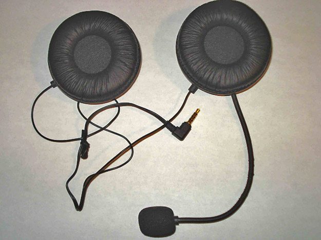
One of the nice features of the BT Interphone is that the speaker and microphone assembly are not hard-wired into the intercom unit; they connect with a 3.5 mm jack (see photo below).
So I decided to replace the small original speakers with a higher quality set.
However, as many owners will agree, without some “know-how” in electronics and little more than a casual soldering skills, the task of speaker swapping may seem overwhelming.
My background in electronics engineering can help me figure things like this out though, so I decided to write this article with a little urging from the editor.
The idea is to assist those who need some direction and step-by-step instructions in performing a speaker upgrade for their intercoms.
Precautions
Before I begin, you must understand that this project involves basic soldering skills (see the A Note on De-Soldering section below) and electronics precautions, such as understanding the issues regarding static electricity and the potential for damaging components when you’re not properly grounded before you start.
As for knowledge of electronics, you need not concern yourselves with impedance matching of Interphone output to speaker. You’d be hard pressed to find a Stereo Headphone with impedance of 8 Ohms in stores.
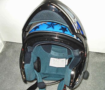
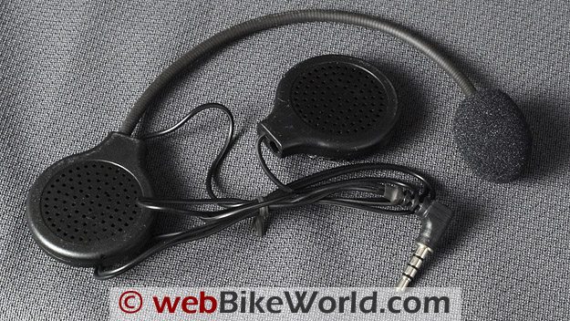 Original speaker and microphone headset on the BT Interphone intercom system.
Speakers or Earbuds?
Many motorcycle riders have expressed an interest in using earbuds for their intercoms rather than speakers, and these instructions also apply to earbuds.
Earbuds are basically a low impedance speakers at 18 Ohms or so for most. Impedance is basically the “total opposition (including resistance and reactance) that a circuit has to passing alternating current.
A high impedance circuit tends to have high voltage and low current. A low impedance circuit tends to have relatively low voltage and high current”. (Impedance FAQ by Bruce Bartlett).
However, mounting the boom microphone on the BT Interphone intercom may be a problem when using earbuds.
If you plan on using earbuds, I suggest leaving the original speakers in place and de-solder the speaker wires and re-solder the earbud wires to the original speaker wires. Then you may be able to leave the mic boom attached to the speaker or intercom unit.
I decided to re-use the original microphone boom that came with the BT Interphone system. A hole can be drilled in the new speaker housing to make it fit. I used an epoxy glue to secure it in place internally.
There may be a few problems with using earbuds inside a motorcycle helmet.
First, the earbud has to be pretty small to fit; i.e., it should be flush with the outside of the rider’s ear or it may be difficult to put on the helmet or the helmet may be uncomfortable to wear.
Also, in-ear speakers may not be legal in all states. The rider would also have to be careful when removing the helmet to not put stress on the earbud speaker wires.
And finally, the earbuds will be hanging inside the helmet when the helmet is removed. One solution to this may be to install male and female jacks to disconnect the earbuds before removing the helmet, but this adds some complexity to the project.
As for comfort level of the earbuds, I’ve used them before in a ride and they’re not too bad, depending on how tight the helmet fits. I do suggest that you use an earbud without a “plastic handle” and instead use the lower profile earbuds of the type that have the wiring coming right out of the buds.
Impedance and Ohms
The majority of the speakers or headphones found in stores will have an impedance in the range of 16 to 32 Ohms. In modern electronics, most of newer devices have variable control components on the output to regulate or protect against overload.
Whether the BT Interphone intercom does or not, I don’t know, but the rule of thumb is to keep the impedance as close to 8 Ohms as possible; that is, the impedance should be as close to the 8 Ohms as possible but not imperative that it is 8 Ohms.
I’m using a 24 Ohm speaker and so far I have no problems or issues. It may be difficult to find 8 Ohm speakers, so again, the rule of thumb is keep the impedance low as possible but, I wouldn’t recommend anything over 24 Ohms since I haven’t tested over that value.
I would also remind the readers that their speaker selection is a personal choice.
Consider the actual size of the speaker and the speaker housing. The speaker of choice must obviously be able to fit into the space in your helmet where the padding around your ears will be.
A too-big speaker will put unwanted pressure on the ears and cause pain (this is where the ear buds are an ideal option). I modified the padding on my helmet to accommodate the speakers I’ve chosen for perfect fitment.
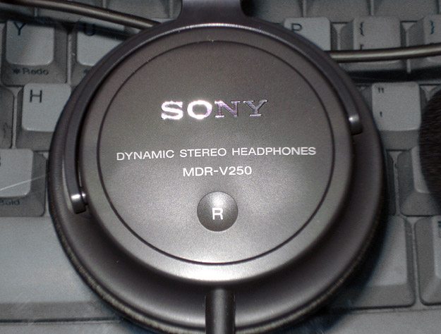
The Sony MDR-V250 headphones were used to replace the standard BT Interphone intercom units.Let’s Get Started
The first thing necessary is to determine the size of the speaker headphone that can be installed into your helmet without making any modifications to the inserts or pads.
In my case, I’ve chosen a stereo headphone by Sony.
It’s called the Sony MDR-V250V Monitor Series Headphones with In-line Volume Control (2015: no longer in production), with an impedance rating of 24 Ohms @1KHz, pictured below.
This unit is “over the ear” type and it should help in cutting out some of the wind noise I encounter at higher speed.
Although the impedance rating is 3 times the original, I’m willing to risk the chance of possible overload by reduction in volume to achieve higher quality and clarity. The choice is yours.
Once the speaker is chosen, it time to do some modification to the original unit. First thing to mod is the speakers. Each speaker housing is held together by one small Phillips head screw.
The speakers are held in place by the glue on the hook-and-loop material. Carefully pry the speakers loose from the housing using a small screwdriver. Try not to cause any damage to components because you might want to reuse them again.
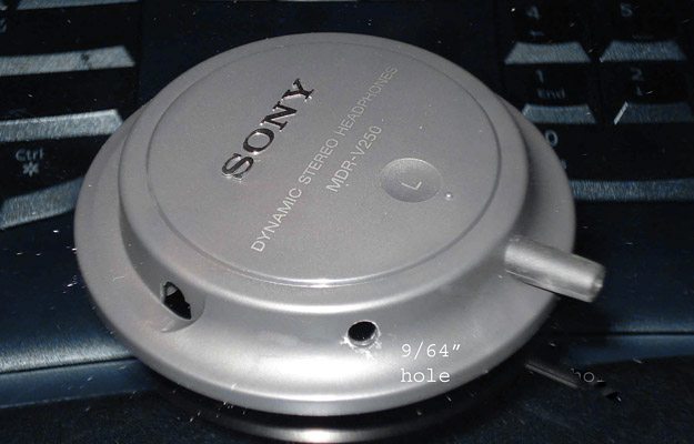
Sony speaker with boom mount hole drilled.A Note on De-Soldering
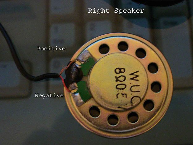
Soldering and de-soldering can begin once the speakers are free from the housing. Prior to any de-soldering, make note of the polarity of the wiring and their colors; I find it helpful to write it down (two photos below).
To clarify the “de-soldering”; there is no need to remove the original solder. With the soldering iron preheated to working temperature, heat the solder until it melt and disconnect the existing wires.
Care must be taken to not overheat the wiring, solder or the PCB (printed circuit board) where the wires are soldered to.
For more information on de-soldering, see this explanation on how to de-solder and here’s aTangent Tutorial video that illustrates how to de-solder.
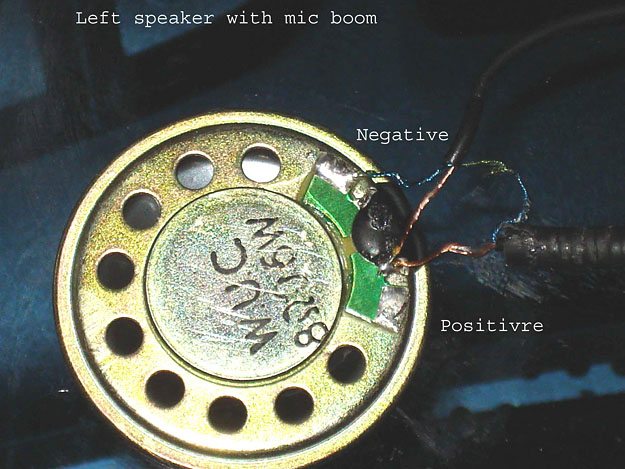
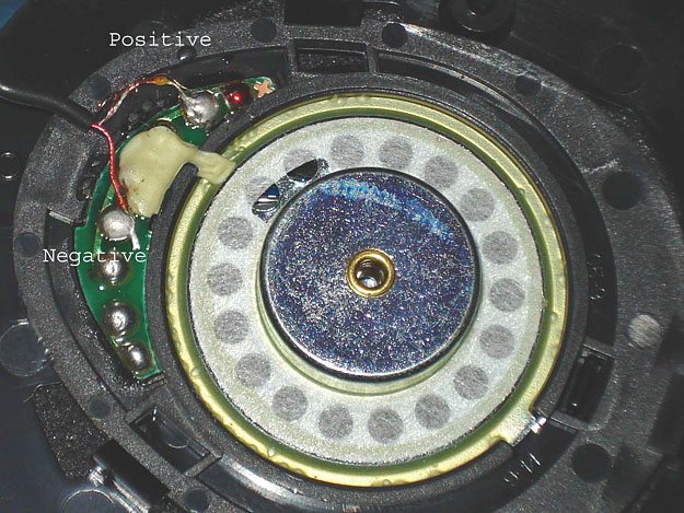
Note the extra wire on the left speaker. The green shielded wire is for the mic boom which is soldered together to the shielded ground wire (blue) of the boom. This is important to remember when disassembling and reassembling into the new speaker later in the steps.
I started with the right speaker since it only had 2 wires to worry about. De-solder both wires and detach the speaker.
Original BT Interphone left-side speaker with microphone boom. Original BT Interphone right-side speaker.Soldering The New Speakers
Going to my new Sony speakers, I started by disassembling the right housing to gain access to the wiring and as before, noting the polarity position of each wire. Note that this speaker actually has an imprint with + on the PCB for positive terminal.
De-solder both wires from the new speaker, solder the wires from the original onto the new speaker with the same polarity orientation and placement, as shown in this photo:
New right-side Sony speaker.At this point, I connected the 3.5 mm audio connector to the BT Interphone and paired it with my cell phone, used as a MP3 player, to test the output and make sure it’s working before moving on.
In my case, it worked but, the volume was little on the low side, as I expected it might be.
The sound quality was excellent compared to the original, which more than made up for the volume.
Modifying the Left Speaker for the Microphone
Now that the right speaker was wired up, I reassembled the housing and complete the right side. We’re half way there.
I imaging this is where most is having difficulty… the left speaker with mic boom. Well, don’t fret, it’s easier than you think.
 Wires from the left-side BT Interphone headset are spliced to the new Sony speaker.
I began by de-soldering the wires from the original speaker. For the time being, leave the green and blue shielded wires together to eliminate any possible confusion.
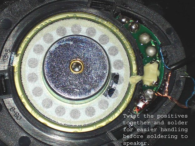
As before, note the polarity and the color of the wires on the new left speaker, which is the same as the right side. Solder the wires onto the new speaker. Both the speaker and the mic boom positives are tied together and soldered to the speaker’s positive terminal. Now for testing…
Again, I connected the 3.5 mm connector to the BT Interphone and paired with my cell phone and tested the speaker as before, it worked as expected.
Now that the speakers are wired-up and working, time to test the mic boom.
With the aid of my wife, we paired our helmets together and asked her to leave the room and relocate to opposite side of the house…to make sure she hear me through the headset and not my voice talking in the room.
New Sony speakers with original BT Interphone headset wiring.So far, so good — everything is working as planned. Now on to modifying the left speaker housing so that mic boom can be mounted.
All I did was to drill a hole a bit smaller than the boom, I used a 9/64″ bit for this, in a place where I wanted the boom to come out (See the photo at the top of the page captioned Sony speaker with boom mount hole drilled.).
Note that I made a little mistake here — the hole should’ve been placed where the wiring can be routed easier into the helmet. Placing the speaker into the helmet as you would want to mount it, then marking the placement of the boom hole is highly recommended.
Once the hole is located and drilled, the trickiest part is next. You must de-solder the mic wires from the speaker, both positives and the negative of the boom (those green and blue shielded wires).
After de-soldering the wires, gently push the wires through the hole drilled in the speaker housing.
It should be very snug. At this point, you may or may not want to enlarge the hole a bit with a sharp knife. Be careful not to over enlarge the hole, you want the boom to go through tightly about ¼” to ½” inside the housing.
The last step is to re-solder the wires back onto the speaker. You might want to get someone to give you a hand with this, it’s tight quarters to work in.
When the wiring is completed, get yourself some epoxy glue, mix it up as directed and put a blob of glue onto the boom where it comes into the housing, but not on the wiring, and making good contact with the housing.
This will cure with time, around 24 hours, and hold the boom in place. See the photo above of the finished speakers and boom, fully functional.
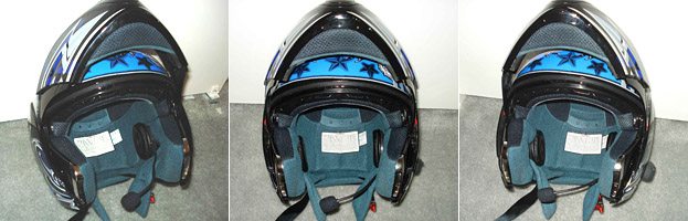
New Sony speakers and modified intercom headset mounted in the helmet.Mounting the Speakers in the Helmet
t’s now time to figure out how to mount the speakers into the helmet.
After some careful considering, I decided to demo the new headphone’s original head piece and use what’s available. I cut the ends off of the head piece and left it on the speakers.
Using a stick-on Velcro, I attached the mount base to the inside of my helmet.
This way, the speakers are not mounted rigidly in single position, it’ll actually pivots to fit where it’s comfortable for me next to my ears (actually, it turned out tighter than I expected when completed).
Depending on brand, construction and type of helmet you own, mine is Full Face Advanced Hawk modular with dual visor, mounting methods will vary from one to another.
Careful consideration need to be made when choosing your headphones as the final fit of the speakers inside your helmet will depend on what you decide.
In my case, as stated earlier, turned out a bit on the tight side because of the size. On the shorter rides, it should be OK but, on the longer rides they may become uncomfortable.
At least this article will help you in the actual swapping of speakers and the mic boom. The rest is up to you to find that “perfect” headphone for your application. Good luck and happy riding.
Publication Date: June 2010
Owner Comments and Feedback
See details on submitting comments.
From “G.O.” (08/10): “The procedure outlined in the article by Tim M worked perfectly on an Interphone F4. I substituted a stereo earphone connection for the 2 replacement speakers.
The resulting clarity, balance, and volume for music and voice communications is outstanding. Thank you!!
The custom IEM’s I like best are Sensaphonic 2x-S (soft silicone). I ride with custom in-ear monitors at low volume. The ride is quiet, so I can focus on traffic and conditions rather than giving screaming truck tires disproportionate attention.
I believe the key to low-volume is sound quality, and IEM’s deliver that consistently for both music and conversation.
HJC Symax II works well for my cranium and riding style. The left ear cushion snaps out, alleviating all cable-routing tedium. Phone/mp3/Pandora/etc. emanate via Bluetooth from a Motorola Droid mounted on the bike’s handlebars and powered from the bike’s battery.
Sadly, Interphone confirmed they don’t offer an earphone jack as part of the F4, so Tim’s article was very inviting. The first stop was Radio Shack for a stereo headphone extension cord that could be sacrificed for the female connector pre-attached to about 10″ of cable. When stripped, the usual 3 leads were available: Right, left, and common ground (unsheathed).
For headphones, there’s no need to disassemble or de-solder the right speaker. The left F4 earpiece was disassembled and de-soldered as Tim described, leaving a red (signal) wire and a black (ground) wire as pictured in the article. Leave the short soldered leads from the microphone untouched in their factory insulation ‘goo’.
I clipped the F4’s right channel cable, a short female connector, about 1″ from the junction of the left channel wires and the microphone wires. When stripped, the F4’s right channel cable revealed an unsheathed ground and a white signal lead.
Twist the unsheathed strands from the F4’s right channel with the unsheathed strands from the headphone cable, pre-solder them, and then attach/solder them to the black lead to the now-detached F4 left speaker. Solder the leads from the F4’s right and left channels to the corresponding leads of the headphone cable.
3/8″ pieces of narrow heat-shrink tubing work well on the exposed solder joints; alternately, electrical tape will work for insulation if applied carefully. As Tim suggests, it’s good to check your work before reassembly.
I found a cheap pair of iPod headphones to plug in initially because I had no idea what post-op volume implications might arise.
To my delight, the impedance differential between the original 8-ohm speakers and the 27 ohm headphones was inconsequential. Volume is great when set at 50% on both the mp3 device and the F4 — no clipping, good balance, and plenty of detail in the sound.
Glue the headphone cable to the plastic housing, leaving the original F4 left speaker removed. Re-glue the plastic back of the F4’s headphone housing that has the hook & loop material on it to the rest of the microphone assembly, route the headphone and F4 command-module cable out the bottom of the helmet, and you’re off to the test ride.
Don’t pass up the opportunity to solicit family approval by placing test calls to and from the helmet with the house phone line. Total time on the project was 1 hour. I’ll be repeating this procedure in about a week on another helmet, and will use a better camera on the next pass.”
From “B.C.” (7/10): “How did you deal with the loss of volume…was the BT headset volume range sufficient or were higher volume (output) settings required on the paired or connected devices…which again, might lead to distortion, etc – more tradeoffs.
I would also be interested in finding out if he has encountered other system issues, including changes in battery duty cycle, etc – all relevant impacts when dealing with the electronics side of it all.”
Tim’s Reply: As to your reader’s questions:
1. I really haven’t noticed any volume reduction on my headset and with the volume at 100% on BT, it’s plenty loud enough for me to hear going 70+MPH.
2. For adjustment on the connected device, I don’t think it’s possible(?). My Sony-Ericsson cell won’t allow me to adjust the volume (more like it makes no change/difference when I adjusting the volume on the phone).
3. For the distortion, I encountered none even with full volume. Distortion will occur if the playback file (MP3) volume is set too high to start. I normally edit all my music using software, such as Nero, to remove pops/distortion/hiss and also to include “volume leveling” to set all the files to have a same level of output sound.
4. For the performance of the BT, I haven’t noticed any difference from original in battery cycle, intercom or use of cell phone. Apparently, what I’ve done to modify has had no “side effects” in my system.
Wife and I will be going on a week’s vacation next week, when we get back, I’ll shoot you an update on the performance of the mod while on longer ride/trip.”
From “M.G.” (6/10): “I pretty much did the exact same thing to my Bluetooth headset that goes into the Nolan N103. I used a set of Iasus XSound2 speakers. I must say it made a huge improvement over the stock speakers that came with the Nolan set up.
The biggest improvement, aside from sound quality, was the amount of volume available. Now, my volume level at its lowest setting is as loud as the stock speakers at a mid level setting. If you own the N103 BT headset, I highly recommend doing this, or finding someone with soldering skills who can do it for you.”