Make Your Own Bluetooth Adapter!
After thinking about it for the best part of two years, I finally purchased an Autocom Active plus intercom system.
It worked brilliantly as promised — straight out of the box!
Having bought the Autocom and laid it out (as suggested in the excellent article by Spyder), I was confronted with the only downside of of a “wired intercom” — the wires!
There was already enough gear hanging off the handlebars, like a UHF and GPS. I needed the cell phone for work contact and since it was Bluetooth equipped it seemed a waste not to use it.
Autocom does sell a Bluetooth adaptor but after shelling out for all the other equipment I could not quite come at another AUD$220. So I decided to build one myself!
The total cost for this unit is around AUD$40 and maybe less depending on what you can beg borrow or er….find.
Soldering (or sodering depending on which side of the Pacific you are on!)… The Bluetooth earpiece is all surface mount devices, and most of them are approximately 1mm in length, so the tracks on the board are barely visible.
You will need some soldering skills and the finest tip you have to complete the work; I used fat-tipped Weller brand iron and had no problems — but I have had lots of practice.
Oh…and be prepared to “butcher “ things (and maybe destroy the odd bit)!
Editor’s Note: Wayne S. generously donated his honorarium for writing this article to Doctors Without Borders (see wBWCharities).
UPDATE: See our review of the Sony Bluetooth Adapter
Safety
Work safely, protect your eyes and hands.
Before you start — read the instructions that came with the Bluetooth earpiece. You need to know how it works before you tamper with it.
The Parts
- 1 x Jabra BT125 Bluetooth earpiece — Why? Because it was the cheapest I could find!
- 1 x Single pole miniature momentary action switch — the on/off switch
- 1 x double pole centre “on”- “off”- “on” momentary action switch for the volume control
- 1 x 2.5mm stereo chassis mount socket — to suit the Autocom standard phone lead
- 1 x suitable case — I used a translucent box to allow the LED indicator to show
- Water resistant covers for the toggle switch levers
- Misc parts — light duty wire, neutral cure silicone (hardware store), heat shrink (small)
Tools Required
- Soldering Iron — preferably temperature controlled fine tipped
- Fine resin cored solder
- Mini side cutters — the sharper the better
- Depending on your eyes, a magnifier of some sort
- Stanley knife or similar
- Multimeter if you have one
Getting Started
First test the Bluetooth earpiece with your phone to make sure it at least worked when you bought it! If it does proceed.
Open up your Bluetooth headset. Some clip together; the Jabra used security headed screws so I had to butcher the case open using a knife. Wave goodbye to your guarantee!
Note where everything is in relation to the the various controls on your earpiece!
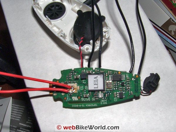 Figure 1: Top of the printed circuit board with connections to ON/OFF/Pairing/”Tap” switch (red wires).
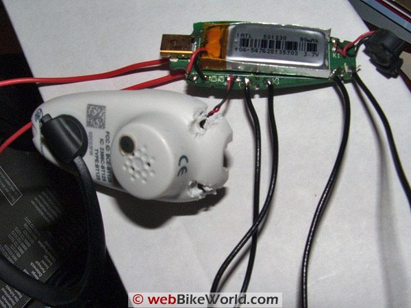 Figure 2: Butchery! And connections to volume pads (black wires)
Cut the red battery lead just a bit away from the board to disconnect it and prevent damage. The little “tail” allows you to temporarily reconnect the battery in later steps.
Carefully remove the PCB (printed circuit board) from the case (the speaker is fixed in the case; leave it for now). Locate the white square on top of the board with the round silvery shape in it. This is the ON/OFF/PAIRING/Tap switch.
Turn the board over (battery side up) and on one side along the edge there are two small devices — these are the volume UP/DOWN switches.
Using a very sharp pair of mini side cutters cut through the centre of each of the volume control switches until you have removed the centre portion of the switch. IF you are careful you will not destroy the solder pads. Do this to both switches.
Turn the board over and go to the white square noted before, using a very sharp blade lift the top LAYER (only) off. You should see a round shiny dot and some other shiny dots arranged around it.
Cut and strip some very light duty hookup wire and tin it, trim the tinned end very short. Next tin the the shiny round dot and one of the other shiny pads, be very careful not to bridge between anything with the solder. Do not use a lot of heat, the pads can be destroyed easily!
Solder one wire to the centre dot and one to the other pad.
Turn the board over, (battery side up) cut 4 more pieces of hookup wire and strip and tin and trim as before. Where each volume control switch was solder a piece of the hookup wire to each of the 4 solder pads.
If you haven’t done so strip and tin the ends of all the connected wires being careful not to break any joints.
You can now re-connect the battery.
Test what you have done by shorting the two wires attached to the dot and other pad, after a period of time the earpiece should boot up and behave like the instructions say it should.
Assuming it works, disconnect the battery and continue.
Cut the wires going to the speaker as close to it as you can. Cut the wires to the Microphone near the Mic. strip and tin each except for the black to the microphone; it will not be used.
Take the 2.5mm stereo socket and some hookup wire, tin the tags on the socket and strip and tin the hookup wire. Identify which terminal touches the tip of the plug when inserted in the socket, connect a piece of hookup wire to the tag feeding the socket and solder this to the red wire that used to feed the Bluetooth microphone — insulate all joints with tape or heat shrink.
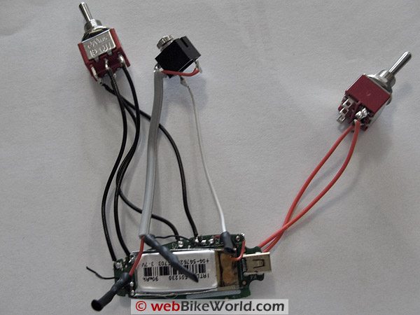 Figure 3: Complete assembly showing connections to switches and socket. Note that there is an unused short black wire at the tapered end of the printed circuit board originally for the Jabra microphone — not used here
The remaining terminal is connected to the red wire that used to feed the Bluetooth speaker. Again, insulate all joints.
Note: The Autocom standard phone lead (phone end stereo type jack):
- Tip = mic
- Ring = speaker
- Top ring = earth
Now install the volume switches. (the two position momentary action centre off double pole switch, hereafter called the volume switch). Operate the switch in one direction and, using the Multimeter, identify which terminals make (normally the pair opposite the direction of switch movement). Now connect one of the volume switch pairs to these terminals.
Connect the other volume switch pairs to the mirror image terminals for the other “pole” of the switch. If this is confusing try the following:
Volume switch looking at bottom terminals:
- 1 — 2 — 3
- 4 — 5 — 6
- Connect one pair to 1 & 2 and the other to 5 & 6
The hookup wires that you previously connected to the switch on the other side (the shiny dot and pad) can now be connected to the momentary action switch. Operate the switch and use the Multimeter to identify the terminals that make. Connect the wires to those terminals.

Reconnect the battery, start up the Bluetooth earpiece and pair it with your phone.
Plug the standard Autocom lead into the AUX 1 of the Autocom and the other end into the socket of the Bluetooth earpiece.
Start up the autocom and test your phone. The instructions that com with the earpiece and phone apply.
All working OK? Next fit it to the case. Make a hole for the charge socket to fit thru making sure the LED is facing up (if using the translucent case).
Fit the switches to the case as you prefer and mount the chassis socket. I tried to make sure that all exposed holes faced sideways or down to minimise water getting inside. Make sure that the board is mounted to allow the LED to be visible through the case.
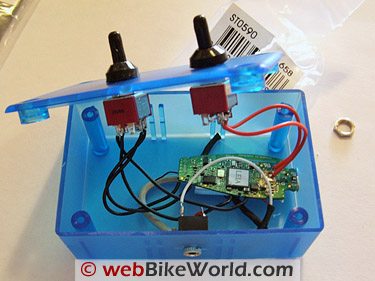
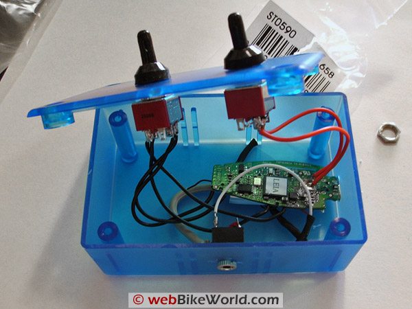 Figure 4: Almost complete, just need to silicone the board into place and close lid. The status LED can be seen through the translucent box. Note that the charge socket needs to protrude through the side of the case to allow charging.
The PCB (printed circuit board) can be held in place using a little neutral cure silicone, don’t go overboard, just use enough to hold it in position and enable you to plug the charger in.
Find somewhere on the bike / trike / whatever and mount the box on Velcro so it can be remove for charging. Run the phone cable from the Autocom to that location.
You should now have completed your Bluetooth adapter. Hope it works as well for you as it did for me.
Can’t get the Jabra mentioned here? Obviously I cannot be 100% sure, but virtually any Bluetooth earpiece or hands-free Bluetooth device should be able to be used. Look on eBay, you may be able to find one cheaper than I did and lessen the risk.
Don’t have an Autocom intercom? Shouldn’t be a problem, the positive (red) from the microphone simply goes to the mic input of the phone lead or socket on your intercom system. The speaker again simply connects to the Speaker and earth respectively.
Publication Date: January 2008
Owner Comments and Feedback
See details on submitting comments.
From “N.B.”: “In case your readers are interested, I recently made my own Bluetooth headset using a few standard products and a 3.5 to 2.5 mm stereo adapter: Kyocera Stereo Bluetooth Headset with Pendant (about $40.00). Tork Sport Motorcycle Headset (about 50.00).
I took the headphone and microphone piece off the Bluetooth set, mounted the pendant to my helmet with some Velcro, I then used a 3 dollar adapter to marry the headset up with my pendant. Paired my phone with the pendant and I was on my way.
Now the downside is that it is by no means an intercom system, but I can listen to my music and receive phone calls as needed. I believe it will also call out but I have never had the need to try. Who do I need to call when I’m riding? That’s me time. The only reason I wanted to be able to use the phone at all was so I could be reached in an emergency. Aside from that, my helmet time is my time.”
Other WebBikeWorld Intercom Posts