1974 Ducati 750 GT Custovation Diary
During my years of riding, restoring and collecting vintage British and European bikes, I fell in love with four distinctive vintage marques.
The muscular engineered Vincent Rapide; the gentlemanly smooth Ariel Square Four; the petite and potent Velocette Venom thumper and the Ducati 750 V-Twin, an Italian blend of engineering, power and seductive good looks. I’ve owned 3 of the four with the Vincent being out of financial reach.
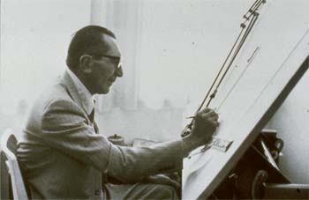
Each machine materialized from the minds of great designers. Phillip Vincent’s HRD-Vincent, Edward Turner’s Ariel Square Four, John Goodman’s Velo Venom and Dr. Fabio Taglioni’s Ducati bevel drive V-twin. All share common attributes of distinctive style, power, sound and engineering excellence for their day. Sadly, three of the four have passed to oblivion but Ducati’s legacy of efficient and practical design lives on in the GT1000 SportClassic, the grandson of the ’74 bevel drive V-Twin.
This diary captures the high points of finding, owning and “custovating” a 1974 Ducati 750GT. Custovation is my word for customizing and renovating the build of a one-of-a-kind vintage motorcycle.
The custovation captures the heritage of the early 70’s bevel drive racers and adds some modern and personal touches to make the bike reliable and safe ride at speed, while maintaining the head-turn factor. This diary is a completely selfish act to preserve the details of the 750 GT custovation events that took place before, during and after with the notion that it inspire or guide others to develop their own custovation project.

 In the Beginning
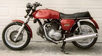
The project bike, a 1974 750 GT was purchased in 1997 from a Norton club friend and he acquired it at an estate sale.
It sat in his garage for two years before the need for more room encouraged him to sell. The bike was about 95% complete and in fairly good condition since the Texas climate and the storage inflicted minimal damage. After acquisition, it sat in my garage for 5 more years, waiting patiently for the start of the project.
During the waiting time, some missing bits were purchased. A lot of tinkering about personal preferences, color schemes and technical issues were noodled around in the gray matter design room between my ears. For inspiration, a montage of Ducati bevel drive V-twin pictures was hung on the shop wall serving as a project compass pointer. That’s the day the flag dropped. In my mind’s eye, I was able to clearly see what the bike should do and how it should look.
The Custovation specs called for a style taken from the genes of the café style bevel drive V-Twins but without the lay-down riding position. Ace style bars and a mono-posto seat with a bum-stop add to the look. Stock engine performance, new suspension, ignition and modern front disc brake system take care of the go, handling and stopping chores.
Oh yeah — it should also borrow the colors that made the 1974 750SS forever famous.
The project was divided into two stages; the frame and all its associated components including electrics and then the engine. I learned the hard way that it’s better to break a long project into manageable chunks. That way, tasks are smaller and have a defined start and finish along with a logical fit with other assemblies of the project. Motivation is fueled when you see steady progress, while the expenses are stretched out.
Before any work was started several information sources were consulted. A collection was made of downloadable manuals, article reprints, picture gallery and parts sources from around the world. Bevel Heaven offers additional information and their parts inventory continues to grow. Various hardcopy reference books were useful too and they’re listed at the end of this article. Most can be found on the net or from bevel drive specialist’s shops.

 Take-Down
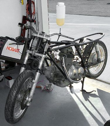
In February of 2002 the motor was started for the last time before the take-down.
The rationale: if the engine runs before it’s taken apart, I know it will run after I put it back together.
The removal was very easy and the engine was set on a dolly until the rolling frame was complete. I imagined a gleaming rolling frame with all parts fitted, anxiously waiting for the engine. Just the kind of inspiration needed for an expected 8-month project.
The speedometer showed 35,000 miles and the Smith’s instruments appeared original, so it’s very possible the reading is accurate.
Compression was low on the front cylinder and fair on the rear. Someone fitted a Dyna –S electronic ignition so a good battery and a squirt of oil in the cylinders, helped get it going.
 No blue smoke so maybe the guides or valves are not worn. The answer to that question will come later. Even in its weakened state the neighbors confirmed that the old bevels drive V-twin’s bark sounded awesome without silencers.
Disassembling the bike down to its major component parts was easy and in a few hours there were several boxes of parts organized and tagged as needed, so three months from now I’ll be able to recall where that weird bolt is supposed to go.
Tiny ferrous metal chips are a tough to remove from the magnetic rotor. Left in place they can cause major damage to the stator.
So as soon as the alternator cover is removed from the bike, cover the magnetic rotor with plastic wrap and tape into place — this will keep any ferrous chips and debris from collecting on the rotor.
Examination of the removed parts revealed the tachometer to be broken, sprocket and chain completely worn, tires while showing deep tread, felt like wood instead of rubber. I had to cut them off with a hacksaw.
.
Wheel bearings either worn or seized, stock Scarab caliper seized, J-model master-cylinder a useless insult, front wheel bearing spacer worn, swing arm spindle rusted, front fork seals leaking, carbs in need of rebuilding, air cleaner plastic box disintegrated, front and rear brakes worn out, Lafranconi silencers more at home on a Guzzi, frayed cables, outdated shocks, the electrical system showed the tell-tale signs of being tinkered with in the past 28 years. Tape balls, green oxidation and extra wires sprouted from the loom.
Several days were spent cataloging replacement parts and their estimated cost. Pills and meditation had little effect to lower my blood pressure, as the estimated price tag for the parts was revealed.
This step is like having a colon exam. You volunteer to have it done but all the time it’s embarrassing and no fun at all. So orders were placed, checks were written and bank accounts were emptied. I kept telling myself “This is the price to pay for custovating a vintage bike”.
With the easy tasks behind, it was time to get serious. This is the part of the project that’s labor intensive, so no matter how much time you estimate it will take, it will take longer.
 For inspiration, I wanted to get something pretty in the garage faster than you could say pasta primavera.
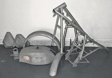
This is where paint and polish gives an adrenalin rush and accolades from your friends. The frame had some rust and grainy paintbrush touch-ups.
After a valiant effort to strip the old paint and remove the rust, I gave up and a professional sand blaster removed all traces of rust and old paint. Best money spent.
The steel frame and trim parts had the ideal textured surface for paint adhesion.
The painter was already on board waiting to receive the blasted parts for primer. The colors, decals and trim scheme were worked out ahead of time so he knew what to do.
While the painter was busy, parts cleaning and polishing started with a vengeance. Polishing aluminum is the dirtiest job on the project but it yields the best rewards. For the next few days my nose sneezed out more aluminum oxide dust than a smelter but the end result produced alloy parts that gleam like chrome.
Only the kick-lever, gearshift, rear brake lever and stay arm will need a trip to the chroming vat. All rough finish cast aluminum parts get a trip through the blaster. After blasting, I usually go over the castings with a stiff stainless steel brush to bring out a long lasting dull but resilient patina
The stock spokes were painted silver, with thoroughly rusted nipples. If you rebuild your own wheels, remember to photograph the lace pattern. Measure the hub offset before cutting off the spokes. I forgot that on the rear wheel but confirmed with others that in fact the hub is centered on the rim.
 As the parts orders arrived and the alloy jewels emerged from buffing wheel, they’re collected in boxes designated for reassembly. Having the majority of the parts in-garage before the build-up starts makes the workflow resemble an assembly rather than start, stop, wait and repeat again.
Surprisingly some of the stock hardware was not rusted due to what appeared to be heavy nickel plating. Big pieces like spacers and large nuts polished up very nicely from a battleship gray to a bright finish.
Throughout this custovation, every fastener was replaced with stainless to the extent possible. Bolts, nuts, lock washers, lock nuts, and locking nuts, including the engine cap head screws.
Stainless wants a smear of anti-size compound on the threads before assembly to prevent galling. For appearance and longevity, stainless can’t be beat. Buying stainless hardware from a wholesaler is about one tenth the cost from a hardware store but not as convenient.
Build-up: Frame Parts
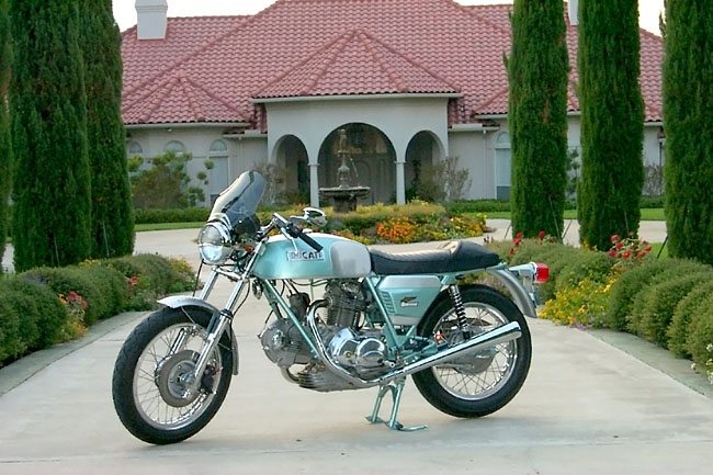
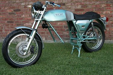
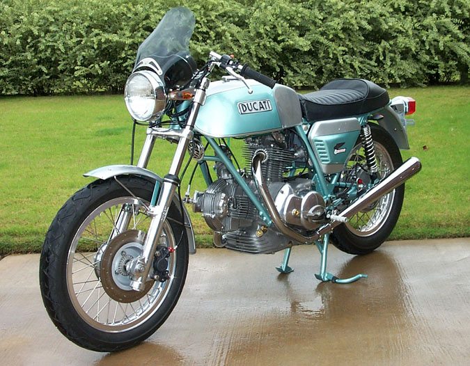
The paint scheme follows in the footsteps of the 750 Super Sport, blending the distinctive silver-gray background with duck egg green. I wasn’t interested in building a SS replica, so while the frame is drenched in green; there is no fairing, clip-ons or rear-sets.
The stock steel tank’s voluptuous shape begged to have the side panels painted green so the new die cast DUCATI emblems would have a place to contrast. The fenders were painted in the same style with a green stripe down the center. The side covers sport vintage Ducati eagle logs and everywhere where green and silver meet, a fine black stripe defines the transition.
Wheel lacing was a gift from my Dad. He showed me how on bicycle wheels, when the dinosaurs roamed the earth. I’m no expert so I work slowly and it comes out right.
There is nothing like lacing stainless steel spokes to a Borrani rim fresh from the buffers kiss. It’s a beautiful sight. During assembly, wear cotton gloves to minimize fingerprints and sweat deposits and use the oil provided, to prevent the nipples from galling.
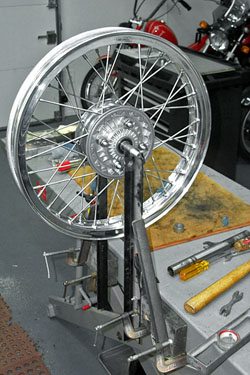 A long while back, I made a simple spoke wheel truing stand that looks homemade but gets the job done. After the wheels were built, Avon Super Venoms with new tubes were mounted easily and look good. In the hubs, the wheel bearings were either seized or grinding, so all bearings were replaced with sealed units.
To keep the racer appearance the stock rubber foot pegs were replaced with knurled pegs with a clear anodized finish.
The Marzocchi front forks were next. The leading axel fork legs have an exotic look. Cleaned, polished and with new seals and caps, the cast Ducati logo proudly shines on their sides.
The swing arm spindle seemed snug during the take-down. However, when it was removed and the rust cleaned away, it shrank, causing the swing arm to develop enough play to cause concern about handling stability.
A new spindle solved the problem and modem shocks with chrome springs connected the back of the swing arm to the frame.
The stock banana seat was in good condition but I wanted a café look. I had it reshaped and covered by a local custom car upholsterer. He cut down, then built-up the foam to produce the classic shape of a bum – stop seat. The custom fit cover has DUCATI embroidered in black on the back panel.
A used stainless chain guard was acquired and polished to cover a low maintenance O-ring chain running on new steel sprockets.
The voluptuous gas tank required new rubber isolators and water-pipe neoprene foam insulation coved the backbone to give the tank a cushy place to rest. A large O-ring secures the tank to the frame nubs
This 750 GT came from the factory fitted with Lafronconi silencers. They were too quiet for my taste and lacked the SS look, so Bub’s Conti replicas were fitted. They’re not Conti’s but are half the price and look and sound just as good.
Dr. Taglioni figured that one disc brake was enough to stop the 750GT with a stock engine and I’m not one to challenge his genius. However, this bike is from an early production run and was fitted with a solid rotor.
To add some style, I drilled a curved pattern of large and small cooling holes in the disk. The Scarab caliper was seized and parts no longer available. So a bolt-on Gremeca caliper fed by a Brembo master cylinder-switch-lever combination was fitted.
If you have an opportunity to refit the master/caliper combination on any bike, be sure to check sources so the two pistons and travel are matched for braking performance, otherwise you’ll have a very poorly performing break system.
A Ducati Monster clutch hose completes the front stopper system. Bleeding the dry system was more trouble than expected but a Mighty-Vac solved the problem.
The original pair of 30 mm Dell’orto carbs was rebuilt and K&N filters added to prevent anything but air from visiting the inside of the combustion chamber. The crankcase breather is also capped with K&N.
The bars are Ace clubman style turned up-side down to relax the seating position and fitted with new electrical controls and tacky black grips. During the Build-Up, plastic bottle caps are taped to the bar ends until the grips were mounted because I almost ripped open my scalp with the bike on the lift.
The rebuilt Smiths instruments looked like new with the intention to keep them that way for as long as possible. Prior to about 1970, shock and vibration failure must not have been a concern because this type of instrument secured directly to the mounting bracket, which was bolted to the triple clamp.
After that, various types of shock mounting were employed to keep the innards of the clocks from self-destructing. The stock Aprilia mount goes the other direction and uses a comprehensive isolation design, hence the big, ugly pod. After 1970, Triumph and BSA instruments were fitted with rubber cups. That type of mounting appealed the most to me since they’re readily available, reasonable price and they fit nicely into the fabricated instrument holder.
To hide the backside of the instruments and add a bit of modern sleek, a AGIVI A-200B smoked mini-windscreen visually pulled together the headlight and instrument package while adding a stylish wind deflector for the rider.
Electrics
Wiring posed its own array of challenges. For the most part the brass connectors were oxidized but otherwise sturdy so cleaning was only a wire brush away.
Since my electrical functions were a bit different than stock, some wires were removed or added to the harness. Marine grade multi-strand wire is the best choice for this type of application. More strands mean more flexibility and that translates to connections that won’t break apart.
A modern style integrated horn, headlight beam selector, turn-signal switch was used in place of the worn out Aprillia switches. The Brembo master cylinder has a more reliable micro-switch to operate the brake light so the pressure activated switch isn’t needed.
All new wires were tape wrapped or sleeved for abrasion resistance and maintain a clean look. The final step was a live electrical test with the battery connected. What a great feeling to see the lights work and voltage show up at the proper places, the style and character of the bike shown through!
The headlamp assembly used the stock headlamp since al halogen would add more drain to the weak charging system. Mounting the headlight shell was a delicate matter of looks and proper fit. Be aware that the clearance between the forks and gas tank is limited, so the new aluminum Tomeselli like support brackets were used.
Turn signals are Lockhart Short Stalk-V’s. The rears are mounted near the shock tops while the fronts are mounted in the headlamp brackets.
The stock horns worked fine but looked large and out of place here, so an aftermarket single unit with chrome face was installed, more for looks than sound power.
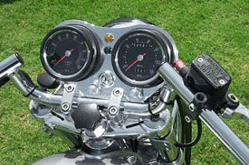 One of the more difficult tasks involved the layout and appearance of the instrument / ignition key / indicator lights. I wanted the key conveniently located next to the speedo, tack and the two indicator lights (turn-signal & high-beam). The stock instrument pod is large and ugly.
So the remedy was a custom cut and polished aluminum plate that mounts in the same place but brings the instruments closer together and tilts them toward the rider.
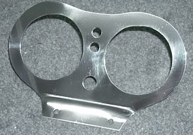 Cutting the plate is actually very easy, but there was a lot of pre-cut fitting, measuring, guessing etc. Cover the plate with wide masking tape to protect the surface while marking and cutting. The end result turned out to be a very good match for the polished clamps and chrome bars.
The voltage regulator and connector panel were cleaned, tested and painted. There’s a lot written about the weak charging system on the early bevel heads and it’s all true.
The best solution is to replace the rotor and stator with untis from a late 90’s ST-2. However, that’s also a thousand dollar plus fix. With the guidance of Willy Gonnason’s expert advice and engineering, I opted to rebuild the regulator with modern semiconductors and install a LED charging indicator. This works well for me since the majority of my riding is during the day.
The original ignition switch was damaged, so a new small automotive unit was wired in but moved to the new instrument panel for better access.
The switch is compact and since it has only three positions switching options are simplified. Off, On – with all but the headlights powered and the other On- adding power to the headlights.
 A previous owner, installed a Dyna-S ignition, but kept the stock coils. One coil was found to be open when the start-up was attempted.
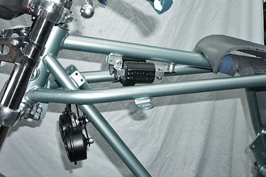
A replacement was used then but for about the same price, modern matching high output Dyna coils were installed ensuring a healthy 30,000-volt lightning bolt to zap the gas vapors.
A homemade aluminum bracket tucks them smartly under the gas tank with outputs pointed down. Resistive plug wires are from NAPA and plugs from NGK.
 The battery is a slightly larger capacity 14 Amp Hour unit to ensure enough power for the bike. The battery compartment base was lined with a piece of spongy doormat material so the battery bottom wouldn’t chafe on the metal mount. Large O-rings or rubber bands cut from an inner tube work well as elastic hold-downs.
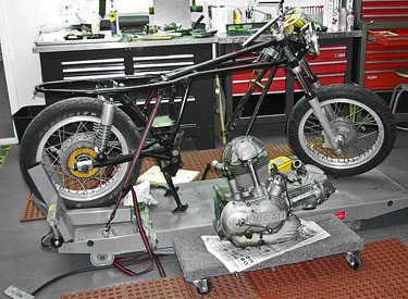
The rolling frame with electrics was finished, so the engine is next.
The Engine
INSPIRATION. That’s what’s sitting in the garage.
The parts are mounted, wiring harness connected and tested multiple times. Yeah, I even shut off the shop lights to see what she looks like during nighttime ride. The complete rolling frame is ready for the engine.
First things first. Since the true condition of the engine internals is unknown, cleaning was a good place to start. That way, if the bottom end and gearbox are ok, that portion of the engine will be ready when the top-end rebuild is complete.
It’s easier to clean the outside of the cases with the top end installed but the huge glob of congealed electricity (read: aluminum) is clumsy to handle.
The bottom cases are scrubbed with carb cleaner, Simple Green and S-100. Use either a stainless steel or hard plastic bristled brush but not brass. Brass leaves a yellow patina that’s difficult to remove.
All the smooth case pieces will have their oxide veil removed and replaced with a brilliant mirror like finish after the buffing wheel plants its kisses. A nice surprise was hiding on the bottom of the engine — the factory case seal was still in place, saying that no one has been in there for 28 years.
Removing the heads was easier but the cylinders were stuck and didn’t release when the heads were removed. Squirting some WD-40 down the cylinder stud holes and applying some propane torch heat and soft mallet to the base immediately released the cylinders.
Be careful where you strike, so the fins don’t break off. The sticky culprit was a rust build-up right at the place where the stud exits the case. The rust made a bulbous deposit that held the cylinder from easy release. I suppose that condensation and external seepage under the stud nut allowed the water to do its nasty work on the stud. I spritzed a little WD-40 and held a big magnet next to the glob while scraping. A stud remover tool was used instead of vise grips prevent tooth bite damage to the studs.
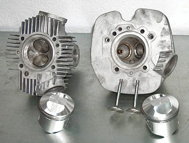
Anxious to understand why the front cylinder had low compression, revealed that the lower compression ring was stuck solid in the piston. The smallest trace of rust was acting like barnacle glue. The rear piston assembly, looked good and both bores while shinny had no scoring or notable ridge.
The piston bodies appeared to be in very good shape with little carbon buildup. The first try to remove the stuck ring simply didn’t work. Freezing, then heating and oiling had no effect.
Then Syd of Syd’s Cycles suggested heating the area behind the ring on the thick inside of the piston with a lot of propane heat. That did it. Picking at the ring made it break into several pieces leaving the piston unharmed. That was ok because the prime concern was for the piston since fresh rings were in the re-build plan anyway.
In the end, it was a waste of time. Measuring the allowed wear parameters of the pistons, bores and rings confirmed that first over pistons with matching bore are needed. That confirmed that the engine very likely has 35,000 miles on it. With that expensive fact in mind, new valves and guides were also fitted to refresh the top-end.
Cleaning the heads and cylinders involved bead blasting. There’s a lot of debate on this cleaning method. Some say hidden grit will immediately kill the engine. Grit is bad for sure.
On the other hand, my experience has been ok in the past. My drill is before blasting: 1) degrease the entire thing then dry; 2) Wire brush clean the sensitive mating surfaces of the head; 3) Tape over the cylinder bores and various cavities and holes leaving only the fins for blasting; 4) After blasting, clean with high-pressure air followed by a thorough second degreasing; 5) The raw casting can then be either steel wire hand brushed to bring back a hard finish with bright patina or final cleaned with S-100 and a stiff non-metallic brush for a softer finish.
Since the engine cases were not split, two internal items needed sprucing up. First, both sludge traps were cleaned. A small butterfly impact wrench works best to remove the slot head screw caps on the crank. There was plenty of packed-in carbon / metal hiding in those holes.
Using a dental pick and solvent sucked by a shop vacuum, emptied them out. Second was the sump and gearbox sludge removal. Kerosene poured in the cylinder holes and oil filler hole worked like a charm. Actually the process was repeated several times until the drained kerosene is mostly clean. A small rag on the end of a parts grabber went inside the oil and filter holes to move things around and eventually soak up any excess kerosene.
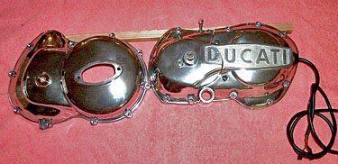 The clutch case bearing was replaced and cover polished along with the alternator side cover.
The gearbox selector case was opened and cleaned and re-packed with moly–graphite grease. These three cover pieces play a big role in defining the beauty of the Bevel Twin engine, so no polishing effort was spared.
The side stand wasn’t used so the engine stud was removed and replaced with a suitable length engine case bolt.
About this time, the top end parts list was made up and shopping started. I should have had the paramedics standing by when the first quote came in. I figured it would be expensive but when the prices came in, my blood pressure dropped and my vision went white. This of course is perfectly natural reaction unless you’re Bill Gates. I had just crossed the Rubicon with this project. There’s no stopping now, especially when it’s just money posing as a roadblock.
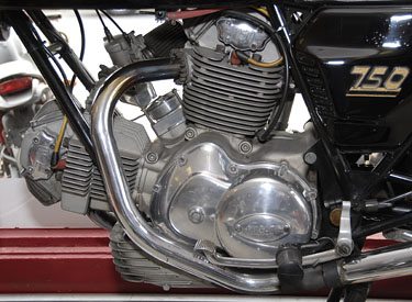
The ignition points housing was polished in-place to not disturb the gear timing. The steel bevel drive tubes looked like two rusty drainpipes so they were replaced by an anodized set from Dr. Desmo.
Both carbs were given a full cleaning and polishing with fresh rebuild parts. Cables are replaced and the choke junction box was freshened up. The choke plays a critical role to make for easy starting.
Guides and valves were replaced along with all the head bearings. The left side bearings were replaced with sealed units, with the exterior side seal removed to boost valve train oil pressure.
The cylinders were bored to the first oversize and mated with beautiful looking JE Pistons. They have a shorter skirt and taller dome than the stock pistons. That taller dome should raise compression just a tad.
Putting it Back Together
The engine top-end is a puzzle of engineered aluminum and steel but now it’s time to assemble the bits.
A temporary assembly was made first to see the main parts fit together and measure the valve to rocker shim sizes before fully mounting them.
 The cylinders were installed on the engine cases first but without the pistons. However, before that, the case-mounting surface was cleaned and the stud holes de-burred to ensure a flat mounting surface.
The stud holes had crud living inside, bits of alloy, steel, rust and oil grunge. A small magnet, dental pick and high-pressure air cleaned the holes like new. Anti-seize was applied to the stud threads.
Before installing the gaskets, notice that the front and rear gaskets are cut to match the case holes. Get them reversed and you can kiss the engine good by.
Pistons were then mounted on the connecting rods. The small end bush was lightly roughed up with emery cloth. My clips had no tang to grab so installing them was a pain.
A test fit of the cylinders and heads, revealed one of the rear cylinder fins cast below the exhaust port was a bit too long and made contact with the cylinder fin, when the head was mounted. The cylinder to head joint does not have a gasket, so the head seal depends on the machined metal-to-metal joint for a seal.
It looked like a manufacturing flaw since the neighbor fins where cut down for clearance. Maybe Giuseppe the inspector had a bit too much Chianti for lunch that day? Some grinding shortened the fin and made the seal tight.
New bearings were installed all around in the heads for a rocker to valve clearance test. Note that the four rockers are identical but can interfere with each other if not installed correctly. The rocker springs need to be opposite of each other to properly center the rocker on the cam. Check that the rockers are centered on the valve stem. Both of my exhausts were off by .012, so additional shims were needed to get them centered.
With new valves and re-ground seats, new valve caps were needed. There’s no screw adjustment on the early 750 GT’s, only fixed space caps. Measure the gap with a stack of feeler gauges to determine the gap of interference, then, order caps that are thick enough to grind down to the correct valve clearance value.
When measuring, make sure the cam is seated next to the bevel bearings otherwise the measurement will vary and the caps won’t fit. I replaced my old Vernier calipers with a digital readout unit for about $30. Best investment ever, and the only way this job can be done.
Installing the built up heads takes some consideration. I was momentarily stalled because it wasn’t immediately obvious how the front head fit. All the books and articles written about rebuilding the Bevel Head only talk about installing the rear head. There are no details about front head installation.
Installing Bevel Heads
Here’s the drill: Align all the engine gear dots. That’s TDC for the rear. Mount the rear head. With its cam and gears installed (with its dots aligned) its at TDC already. Fasten it down to 30 ft lbs.
Then take the front head: with the rockers removed, install the cam and vertical drive, aligning their dots. Snug tighten at this time. Rotate the cam so the lobes are at 4 and 8 o’clock, (that’s TDC for the front) then mount on the cylinder. It fits right in. Fasten head bolts to 30 ft-lbs. Then install the rockers, mount the cam bearing support. Secure the cam nut lock washer now.
Setting the proper torque for the head bolts is another dilemma. Torque spec is 30 ft-lbs, however, there’s no room for a conventional socket-end torque wrench. Only an open-end wrench works. Having no other alternative, I practiced to get the feel of 30 ft-lbs. I clamped an old bolt with nut in the vise and tightened with the torque wrench then the same with the open-end. A few times back and forth and I think I got a feel for the torque needed.
At this point the engine was finished enough to mount in the frame. The side covers were not installed yet since they’ll get in the way. Mounting the engine is a breeze — three bolts and that’s it.
Light at the End of the Tunnel!
A genuine simulated gold link O-ring chain made sure those Italian ponies make their way efficiently to the rear wheel. The drive chain on bevel drives has a tendency to score the engine case so this was a good time to fit a Case Saver form Bevel Heaven. Mind the instructions to locate the saver in the exact spot. When it’s there, the chain has a clear path above the cast alloy housing.
I removed the Dell’Orto chokes to simplify the engine layout. I learned that for easy one kick starting the choke is needed. The original setup uses a square metal box as a junction place. My cables were worn and I didn’t want to locate the choke lever on the handlebars, so I used an Amal 2 into 1 throttle connector. The cables were replaced and an Amal choke lever located under the right side of the tank. And guess what? The bike starts on the first kick now!
Adding the freshly polished alternator and clutch side covers was like jump-starting a flat-line heart failure. The bike seemed to pop to life. Not a full, hop off the table jump, but the kind that makes the paramedics grin when they know the patient took their first step toward a new life.
Finished at Last
It was about this time the 750 GT acquired a new name: The Texas Duke.
The first start-up of the Duke was a momentous occasion. I made this a family event since my infinitely patient wife, Beverly, and our family of sons, daughter, grandchild and their spouses, all have an interest in riding. They all appreciate fine vintage machinery and art in their own way. So one Friday evening we assembled in the garage for the Duke’s début.
There he sat a dandy in alloy polish splendor. Sporting new pistons, rings and valves, along with modern technical refinements like electronic ignition, fine Italian brakes from Brembo, the SS like paint job, stainless everything that can be stainless and tires from the land of Avon.
He was welcomed back into the world of two wheel motor-sports with a hearty SALUTE’! We toasted fine red Italian wine from the vineyards near Bologna while Andrea Bocelli sings in the background. This small but faithful group of Italian motorbike lovers cheered, Benvenuto a la Duke!
He cleared his throat of fresh oil and Lubriplate. Another kick and he roared back at us just as I expected him to. Loud, authoritative and commanding a presence in the garage, I’m The Duke and I’m BACK!
What a beautiful Bevel Head — a sight and sounds to behold. Just like seeing your kid receiving a college diploma. All the hard work and expense paid off, cigars were lit and smoke rings filled the air.
One more toast, to Dr. Fabio Taglioni. He’s gone but his spirit will remain an inspiration to Bevel Head lovers and the Texas Duke.
750 Bevel Head Rebuilding and Restoration Tips
Some pointers that may save you time and effort rebuilding a Bevel Head
Ignition timing (with Dyna-S Ignition)
Tools Needed:
• Indicator light
• Piston Stop tool
• Degree wheel and wire pointer
Rotate engine to just before top dead center – the exact distance is unimportant, then screw your tool into the cylinder head, unlock the locknut and thread the rod down until it touches the piston crown, relock the nut.
The important part is to stop the piston going over TDC, then place your degree disc on the crankshaft and fix up a pointer in the normal manner. Next turn the disc to where you think it should be, again accuracy is not all that important at this stage, next turn engine so that the piston is hard up against the rod of your TDC tool.
Now look at your degree disc, say it reads 42 degrees BTDC (before top dead center) make a note of that figure, now turn engine backwards until piston rises and contacts the TDC tool once again. Holding in hard contact look at degree disc, this time say it reads 18 degrees ATDC (after top dead center).
Now comes the interesting part, add your first reading (42 degrees BTDC) to the new figure (18 degrees ATDC), resulting in 60. Now divide 60 by 2 and you have 3O degrees so still holding engine against the stop move your degree disc to read 30 degrees ATDC, to check if you are correct, rotate the engine forward again until the piston contacts the stop and check the disc – it should read 30 degrees BTDC.
Next, remove TDC tool and turn engine till disc reads 0 degrees; this will be true TDC. Easy isn’t it?
But just in case, another example: Engine contacts stop at 61 degrees BTDC, turning the engine back the other way stop contacted at 33 degrees ATDC. 61 plus 33 = 47 degrees. So set the disc to 47 degrees ATDC to check, rotate the engine backwards and the reading should be 47 degrees, BTDC.
Remove tool and set engine to 0 degrees as indicated on the disc. As will be seen by the above, the action of holding the piston hard against the stop from both directions removes any inaccuracies due to the various engine clearances. This results in a true TDC impossible to reproduce by other methods.
Note: For beginners, the Ducati Bevel drive twin runs backwards, so don’t get your BTDC and ATDC confused.
Rear Brake Cable
To ensure smooth rear brake return action, make sure the foot lever cable point is lined up with the frame cable stay. The cable should travel in a straight line out toward the rear wheel. If not, heat and bend the foot lever cable lever to line up. Next I used a rubber coated cable clamp large enough for the cable to pass through. This was located the left silencer mounting bracket. It keeps the cable running straight for about 10 inches.
Rear Brake Light Switch
The switch that’s mounted on the cable is useless and not easily removed. I replaced its function with a universal rear brake light switch by drilling a small hole in the foot lever cable lever for the spring to attach. The other end is mounted using a rubber cable clamp to the frame tube holding the silencer bracket.
Slipping Clutch
My bike had been sitting unused for more than 6 years. I left the clutch alone during the rebuild waiting to see what it needed once it was road worthy. Sure enough, even though the slack adjustment was correct, the clutch slipped under acceleration.
Examining the steel plate and friction plate stack, the thickness was greater than 1.19 inches per the wear spec so I assumed it wasn’t worn out. The friction material showed that the surfaces appeared glazed but not from use, rather something was on the surface.
So I washed them in solvent. Very risky but I was sure it wouldn’t hurt the material and not leave any oily residue like kerosene. Sandblast the metal plate with 100-grit aluminum oxide. Place the plates on a flat metal surface while blasting to prevent warping then replace the springs with a heavier coil than stock.
Valuable Ducati Custovation Resources
-
Ducati Owners Club Victoria Australia – Articles about bevels and other relevant technical subjects
-
Wheels Unlimited – Tim and Tom Frutiger (507) 288-5630 Ducati and Norton parts and service
-
Bevel Drive Information – Devoted to all aspects of the bevel drive with downloadable files of shop manuals, magazine reprints, supplier links and much more.
-
Bevel Heaven – Delrin case saver
-
Bub’s Inc. – Conti look-alike silencers
-
Countryside Cycle Shop – Rubber cups for Smith’s instruments
-
Dyna Performance Electronics – Dyna-S electronic ignition and coils
-
Flanders M/C Accessories – Ignition switch, electrical controls
-
JE Pistons – High quality, performance pistons and rings
-
Nisonger Automotive – Experts in Smith’s instrument repair
-
Progressive Suspension – Rear shocks and springs
-
Storz Performance – Gremica caliper (replaces Scarab) Steve Storz
-
Syd’s Cycles – 727-522-3333. Syd and Malcolm Tunstall; No web site, catalog available. St. Petersburg, Florida. Decades of bevel drive expertise bevel parts, body parts and engine work
-
Willy Gonnason – Ducati Roundcase Bevel Engine Alternator Conversion
Bevel Drive Twins and Ducati Restoration Books
-
Ducati Gold Portfolio 1974-1978 – Road and comparison tests, specifications, technical data, rebuilds, tuning.
-
Ducati Twins Restoration Guide: Bevel Drive 1971-1985 – Authentic restoration guide BY Ian Falloon
-
Haynes Ducati Twins Early 70’s – Repair manual out of print
Owner Comments and Feedback
See details on submitting comments.